Capacitor flexible conductor automatic welding machine

An automatic welding machine and flexible wire technology, applied in the direction of circuits, connections, electrical components, etc., can solve problems such as high labor costs, troublesome management and production, and incoherent welding processes, so as to improve automatic processing, facilitate management and production, Effect of improving processing efficiency

Inactive Publication Date: 2007-12-05
孔星
View PDF0 Cites 11 Cited by
  • Summary
  • Abstract
  • Description
  • Claims
  • Application Information

AI Technical Summary

Problems solved by technology

[0003] The welding procedure of existing electric capacity, soft wire generally comprises the following steps: wire straightening and wire stripping---twisting wire---welding; above-mentioned operation step is finished by different equipment and manpower respectively; Between the wire twisting process, and between the wire twisting and the welding process, because there is no upper clamping device that can clamp the wires, the welding process of the existing capacitors and soft wires is incoherent, and different equipment and manpower are required. Finish
Therefore, the existing welding equipment for capacitors and flexible wires has the following disadvantages: (1) The welding process is incoherent and needs to be completed by different equipment and hands, which not only has high labor costs and low efficiency, but also easily leads to defective products. (2), the entire welding process is completed by multiple independent equipment, which brings a lot of trouble to management and production; and cannot meet the requirements of automated production

Method used


Image

  • Capacitor flexible conductor automatic welding machine
  • Capacitor flexible conductor automatic welding machine
  • Capacitor flexible conductor automatic welding machine

Examples


Embodiment Construction

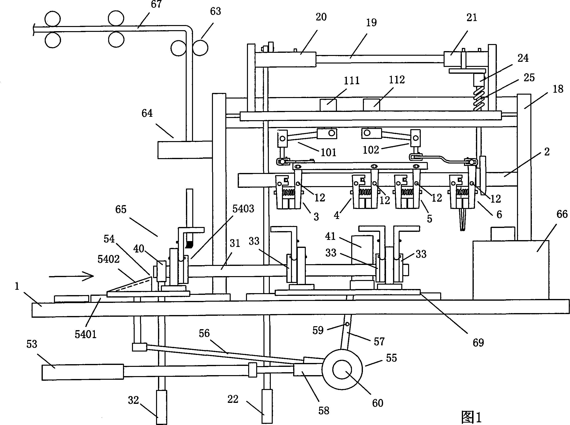
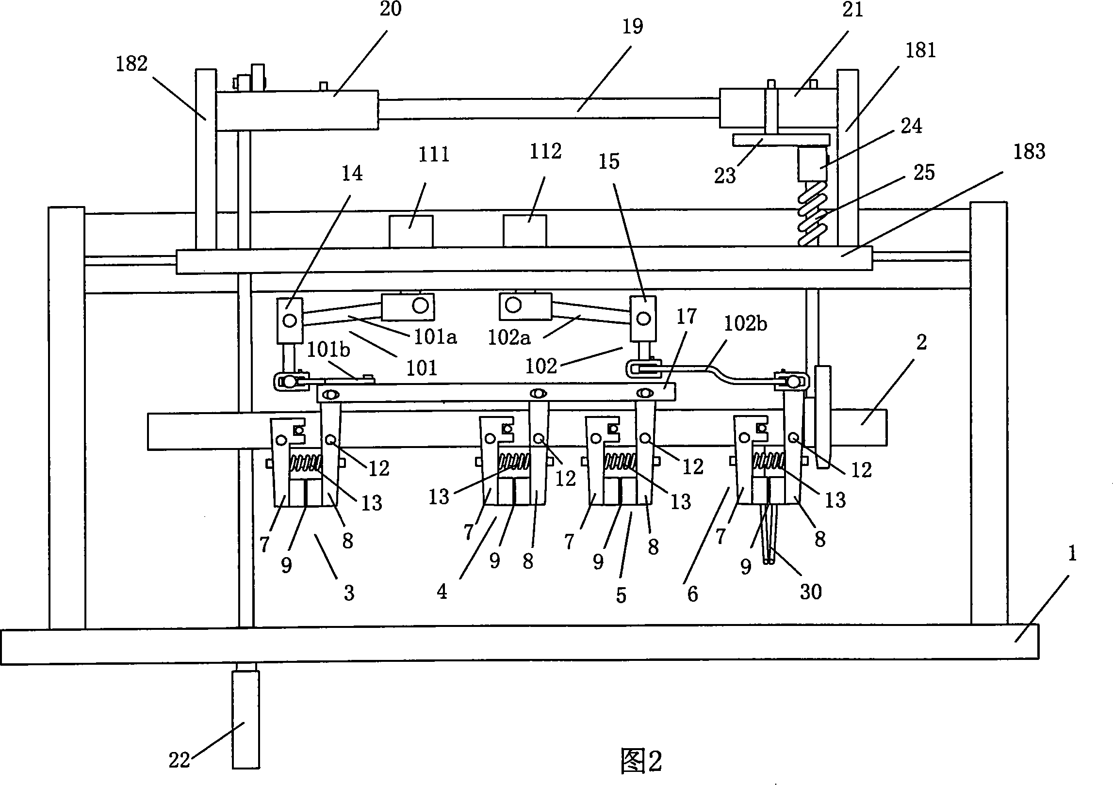
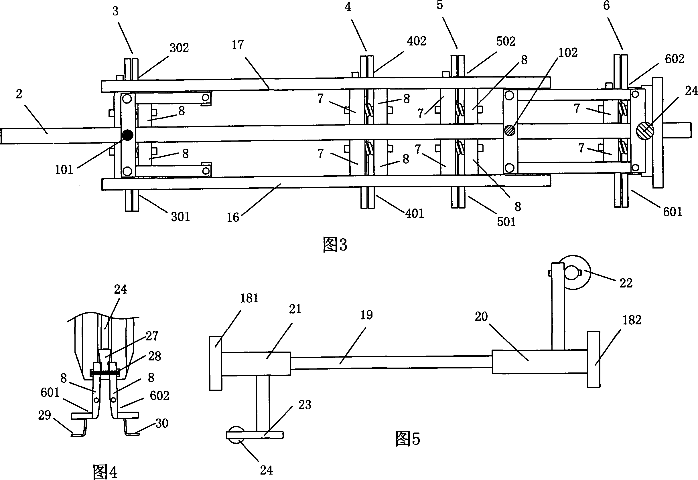
[0033] As shown in Figures 1 to 5, an automatic welding machine for flexible capacitor wires includes a frame 1 on which a wire straightening device 63, a wire stripping device 64, a wire transfer device 65, and a welding device 66 are arranged. 1, between the wire transfer device 65 and the welding device 66, upper and lower clamping devices 68, 69 of the wires are also provided. The upper clamping device 68 is equipped with a mounting plate 2 on the frame, and the mounting plate 2 At least two pairs of upper clamp arm assemblies 3, 4, 5, 6 are provided, and each pair of upper clamp arm assemblies 3, 4, 5, 6 consists of two adjacent left and right upper clamp arm assemblies 301, 302; 401, 402; 501, 502; 601, 602, each of the upper clamp arm assemblies 301, 302, 401, 402, 501, 502, 601, 602 includes front and rear arm bars 7, 8, front and rear arm bars The lower ends of 7 and 8 form an upper clamping opening 9, and each upper clamping arm assembly 301, 302, 401, 402, 501, 502,...


PUM


Abstract

The invention publishes an automatic welding apparatus of electric capacity soft wire, on the rack has establishes the wire straighten installment, the wire peeling installment, the wire transfer device and the welding plant, on the rack also establishes the wire top and bottom holding device between the wire transfer device and the welding plant, the top holding device is equipped with the mounting panel on the rack, on the mounting panel has establishes at least two pairs of top clamp arm module, the each pair of the top clamp arm module is composed of the left and right two top clamp arm module, the each top clamp arm module includes the former, back arm perch, the below end of the former, back arm perch forms the up clamp hold mouth, each up clamp arm module also includes the movable former arm perch or back arm perch, the one end of the pull organization which opens the up clamp hold mouth connects to the gas jar, the former, back arm perch which connects the another end of the pull organization has the fulcrum, between the former and back arm perch has equipped with the reposition lug reed. The invention has saved the labor cost, raised the production efficiency effectively, and realized the automated production.

Description

[0001] Technology area [0002] The invention relates to an automatic welding machine for capacitors and flexible wires. Background technique [0003] The welding procedure of existing electric capacity, soft wire generally comprises the following steps: wire straightening and wire stripping---twisting wire---welding; above-mentioned operation step is finished by different equipment and manpower respectively; Between the wire twisting process, and between the wire twisting and the welding process, because there is no upper clamping device that can clamp the wires, the welding process of the existing capacitors and soft wires is incoherent, and different equipment and manpower are required. Finish. Therefore, the existing welding equipment for capacitors and flexible wires has the following disadvantages: (1) The welding process is incoherent and needs to be completed by different equipment and hands, which not only has high labor costs and low efficiency, but also easily lead...

Claims


Application Information

Patent Timeline
Patent Type & Authority Applications(China)
IPC IPC(8): H01R43/02H01R43/28
Inventor 孔星尤枝辉曾业强秦岭
Owner 孔星
Why Eureka
Try Eureka