Numerical control milling and drilling device for roof of train

A processing device, drilling and milling technology, applied in the direction of feeding device, metal processing, metal processing equipment, etc., can solve the problems of difficult control of positioning accuracy, restricted production capacity, inconvenient maintenance, etc., achieve stable processing accuracy, guaranteed processing quality, The effect of improving work efficiency

Active Publication Date: 2013-01-16
深圳市威远精密技术有限公司
View PDF9 Cites 10 Cited by
  • Summary
  • Abstract
  • Description
  • Claims
  • Application Information

AI Technical Summary

Problems solved by technology

A small number of companies have purchased semi-automatic processing devices from Germany's Siemens, which are expensive and inconvenient to maintain
Although the latter has made some progress compared with the manual processing method, when the processing position changes, the displacement of the drilling and milling head is still adjusted by manually turning the handwheel.
Its positioning accuracy is difficult to control, and the positioning method is cumbersome and complicated, requiring several people to work together
For this reason, it cannot meet the requirements of machining accuracy and efficiency of train carriages, which restricts the production capacity

Method used


Image

  • Numerical control milling and drilling device for roof of train
  • Numerical control milling and drilling device for roof of train
  • Numerical control milling and drilling device for roof of train

Examples


Embodiment Construction

[0022] The technical scheme of the present invention is described in detail below in conjunction with accompanying drawing:

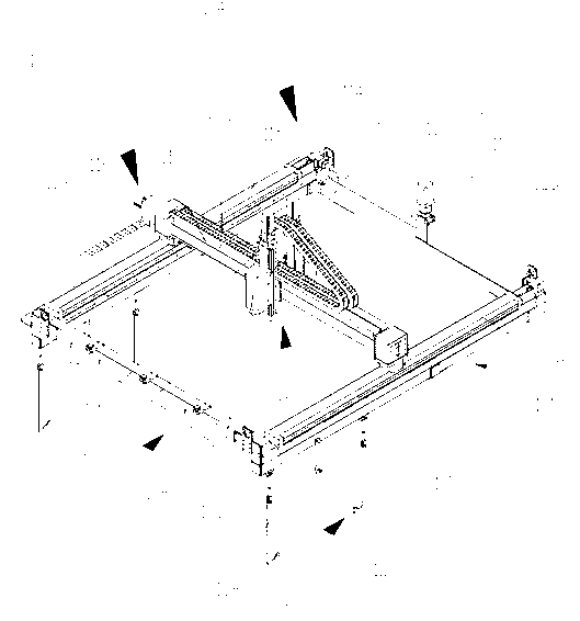
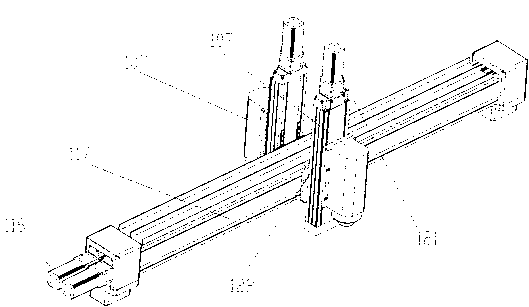
[0023] see figure 1 Schematic diagram of the structure of the CNC drilling and milling device for the train roof of the present invention and combined figure 2 Schematic diagram of the base structure of the numerical control drilling and milling processing device for the train roof of the present invention.

[0024] As shown in the figure, the numerical control drilling and milling device for the train roof includes: a base 101, a base positioning mechanism 102, a base fastening mechanism 103, an X-axis motion mechanism 104, a Y-axis motion mechanism 105, a Z-axis motion mechanism 106 and At least one working end 107, wherein, the base positioning mechanism 102 and the base fastening mechanism 103 are both arranged on the base 101, and the X-axis motion mechanism 104 is arranged on the base 101 and is connected to the base 101, the Y-axis motion mech...


PUM


Abstract

The invention relates to a numerical control milling and drilling device for the roof of a train, which comprises a base, a base positioning mechanism, a base fastening mechanism, an X-axis movement mechanism, a Y-axis movement mechanism, a Z-axis movement mechanism and at least one working end. The base positioning mechanism and the base fastening mechanism are arranged on the base. The X-axis movement mechanism is arranged on and connected with the base. The Y-axis movement mechanism is arranged on and connected with the X-axis movement mechanism. The Z-axis movement mechanism is arranged on and connected with the Y-axis movement mechanism. The working end is arranged on the Z-axis movement mechanism. The numerical control milling and drilling device for the roof of the train can automatically perform face milling, hole drilling and tapping in the stroke range after being primarily positioned and stabilized. Compared with machining by manually climbing the roof and machining of a semi-automatic device of Siemens, the numerical control milling and drilling device at the roof of the train is more accurate to position, higher in machining precision and stable, and the machining quality is ensured, the work efficiency is improved exponentially and the numerical control milling and drilling device for the roof of the train is safe and reliable.

Description

[0001] The invention relates to a drilling and milling processing device, in particular to a numerical control drilling and milling processing device applied to the top of rail transit train carriages such as EMUs, light rails and subways. Background technique [0002] Since the train compartment is the living and resting space for passengers during the journey, in order to ensure the comfort of passengers during the journey, all pipelines for water supply, power supply, air supply and ventilation and cooling facilities must be arranged on the roof of the train, and then enter the corresponding position inside the compartment. For this reason, it is necessary to open the slots for laying out pipelines and trim the planes of local parts at the top of the train car to facilitate installation. [0003] In recent years, my country's high-speed rail construction has advanced by leaps and bounds, and has achieved a leap-forward development. At the beginning, it introduced advanced fo...

Claims


Application Information

Patent Timeline
Patent Type & Authority Applications(China)
IPC IPC(8): B23P23/00B23Q5/28
CPCB23Q1/26B23Q5/36B23Q5/40B23Q37/005B23Q2705/18
Inventor 李敬宇李一前周盛军许记伟
Owner 深圳市威远精密技术有限公司
Why Eureka
Try Eureka