Noise isolation device for building tapping

A technology for noise and holes, applied in the field of isolation devices, can solve problems such as excessive physical strength, large noise, and cost, and achieve the effect of reducing noise, reducing noise, and increasing noise reduction effect

Pending Publication Date: 2022-03-25
陈有文
View PDF0 Cites 0 Cited by
  • Summary
  • Abstract
  • Description
  • Claims
  • Application Information

AI Technical Summary

Problems solved by technology

[0004] In order to overcome the shortcomings of manual direct control of the punching machine to open the building, not only will it produce a lot of noise, but also the control of the punching machine requires more physical strength, and it is inconvenient to drill holes in the high position of the building. The technical problem to be solved is : Provide a kind of noise isolation device based on construction opening that can conveniently control the opening of the punching machine and effectively eliminate noise

Method used


Image

  • Noise isolation device for building tapping
  • Noise isolation device for building tapping
  • Noise isolation device for building tapping

Examples


Embodiment 1

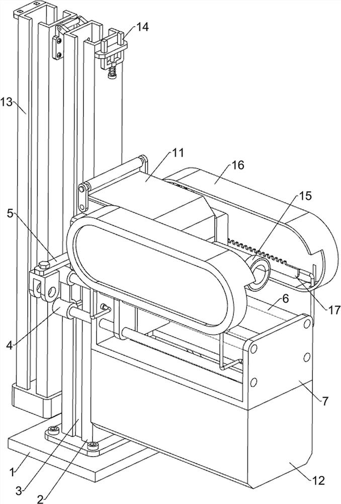
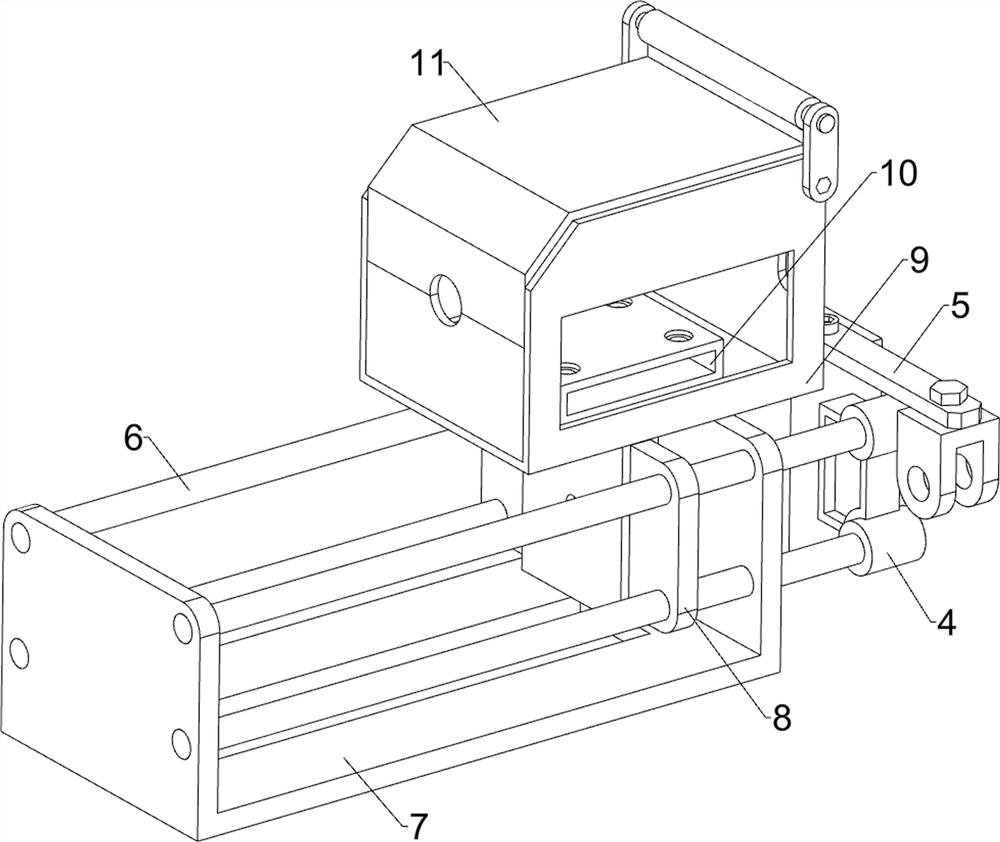
[0036] A noise insulation device based on building openings, such as Figure 1-9 As shown, it includes a bottom plate 1, a guide frame 2, a support block 3, a first sliding block 4, a connecting frame 5, a cross bar 6, a frame plate 7, a first sliding plate 8, an airtight frame 9, a mounting frame 10, and a cover plate 11. The moving assembly 12 and the extension assembly 13, the upper side of the bottom plate 1 is fixed with a guide frame 2 through bolts, the lower side of the guide frame 2 is provided with a support block 3, and the inner side of the guide frame 2 is slidingly provided with a first sliding block 4 , the first sliding block 4 is in contact with the support block 3, the upper side of the first sliding block 4 is connected with a connecting frame 5, the front and rear sides of the connecting frame 5 are provided with bolt holes, and the upper and lower sides of the left part of the first sliding block 4 are The front and back are symmetrically connected with cr...

Embodiment 2

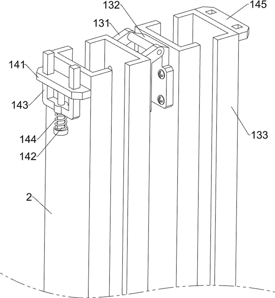
[0043] On the basis of Example 1, such as figure 1 , image 3 , Figure 4 , Figure 10 , Figure 11 , Figure 12 , Figure 13 , Figure 14 , Figure 15 and Figure 16 As shown, it also includes a fixed assembly 14, the fixed assembly 14 includes a guide plate 141, a guide rod 142, an insert block 143, a second spring 144 and a clamping plate 145, the upper left side of the guide frame 2 is connected with a guide plate 141, the guide The lower side of the plate 141 is connected with a guide rod 142, the guide rod 142 is slidably connected with an insert 143, the two ends of the insert 143 are slidably connected with the guide plate 141, and the bottom of the insert 143 is connected with the bottom of the guide rod 142. A second spring 144 is connected between them, and a clamping plate 145 is connected to the upper right side of the elongated frame 133 , and the clamping plate 145 cooperates with the inserting block 143 .

[0044] When the height of the guide frame 2 i...


PUM


Abstract

The invention relates to an isolation device, in particular to a noise isolation device for building tapping. According to the noise isolation device for building trepanning, trepanning of a perforating machine can be conveniently controlled, and noise can be effectively eliminated. A noise isolation device for building tapping comprises a bottom plate, a guide frame, a supporting block, a first sliding block and the like, the guide frame is fixedly connected to the upper side of the bottom plate through bolts, the supporting block is arranged on the lower side of the guide frame, the first sliding block is arranged on the inner side of the guide frame in a sliding mode, and the first sliding block makes contact with the supporting block. The lengthened frame is controlled to rotate anticlockwise with the joint of the fixed plate and the rotating plate as the axis, so that the lengthened frame is rotationally located on the upper side of the guide frame, the first sliding block can move into the lengthened frame, higher building positions can be conveniently punched, and a sealing frame can effectively isolate noise generated during operation of the punching machine.

Description

technical field [0001] The invention relates to an insulating device, in particular to a noise insulating device based on building openings. Background technique [0002] When decorating a building, it is often necessary to make holes in the building. Generally, to make holes in the building, the punching machine is manually held, and the punching machine is controlled to make holes according to the places that need to be punched. , when the drilling machine is in operation, it will make a lot of noise, and the drill bit of the drilling machine will also produce noise when it contacts the building. Therefore, when the building is drilled, it will disturb the rest of the surrounding residents and affect the harmony of the neighborhood , and manually directly control the punching machine to drill holes in the building, it needs to consume more physical strength, and it is inconvenient to drill holes in the high position of the building. [0003] Therefore need to design a kin...

Claims


Application Information

Patent Timeline
Patent Type & Authority Applications(China)
IPC IPC(8): B28D1/14B28D7/00G10K11/16
CPCB28D1/14B28D7/00G10K11/16
Inventor 陈有文
Owner 陈有文
Why Eureka
Try Eureka