Eureka AIR delivers breakthrough ideas for toughest innovation challenges, trusted by R&D personnel around the world.

Equipment cabinet system and exhaust equipment thereof

A technology for exhaust equipment and cabinets, which is applied to electrical equipment casings/cabinets/drawers, cooling/ventilation/heating transformation, electrical components, etc., which can solve problems such as high server temperature, server damage, and uneven heat dissipation, and improve heat dissipation efficiency , Reduce the air work, reduce the effect of energy loss

Active Publication Date: 2013-07-24
DELTA ELECTRONICS INC
View PDF2 Cites 10 Cited by
  • Summary
  • Abstract
  • Description
  • Claims
  • Application Information

AI Technical Summary

Problems solved by technology

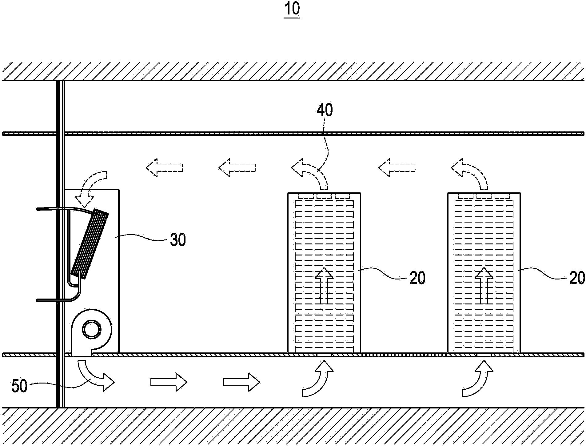
[0004] However, there is still a distance between the rack 20 and the cooling device 30, and the cold air 50 is blown into the rack 20 through the bottom of the rack 20, so it is easy to cause uneven heat dissipation, resulting in the temperature of the server at the bottom of the rack 20. lower, but the temperature of the server at the top of the rack 20 is higher; in addition, when the cooling device 30 fails, the above-mentioned closed cabinet 10 has no corresponding measures, and in severe cases, the heat is continuously accumulated in the closed cabinet 10, resulting in The server is damaged; moreover, when the external environment is low temperature, the temperature of the hot air 40 is not high, but the above-mentioned cooling device 30 must still operate continuously, which may cause waste of resources

Method used


Image

  • Equipment cabinet system and exhaust equipment thereof
  • Equipment cabinet system and exhaust equipment thereof
  • Equipment cabinet system and exhaust equipment thereof

Examples


Embodiment Construction

[0057] The detailed description and technical content of the present invention will be described as follows with reference to the accompanying drawings, but the accompanying drawings are for illustrative purposes only and are not intended to limit the present invention.

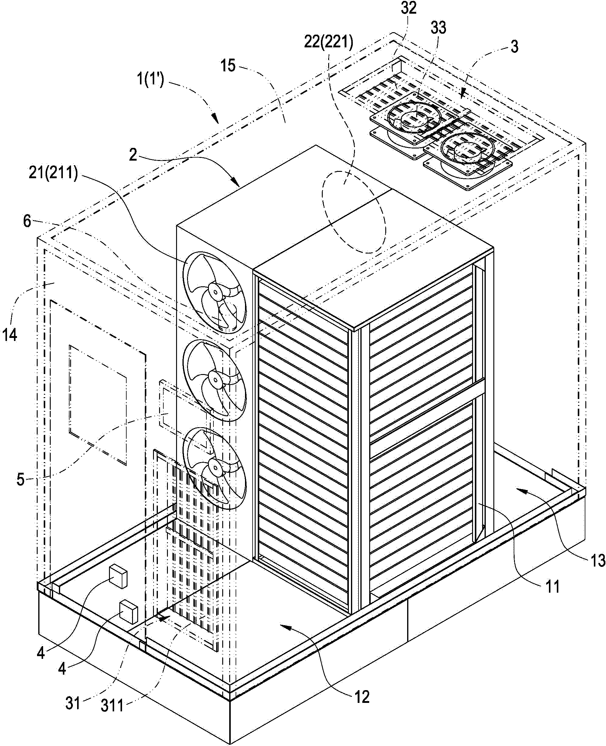
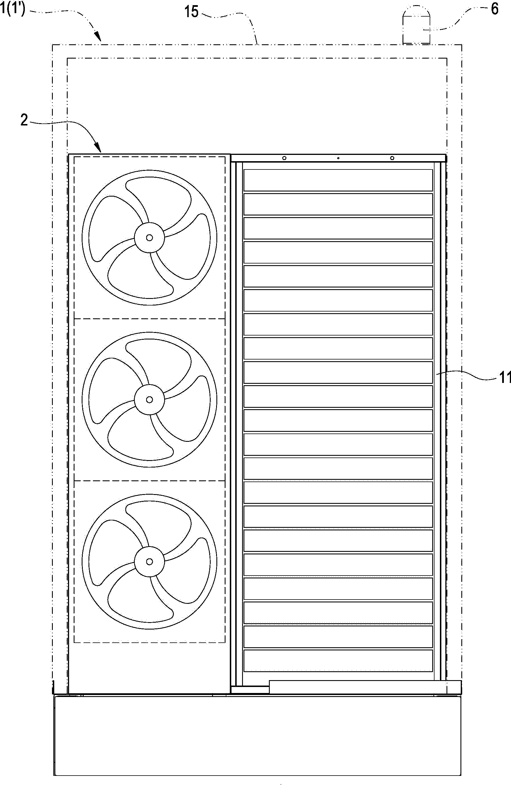
[0058] Such as Figure 2-Figure 4 As shown, the present invention provides a cabinet system and its exhaust equipment. The cabinet system mainly includes a closed cabinet 1 ′, a frame 11 and a cooling device 2 .

[0059] The rack 11 is arranged in the airtight cabinet 1 ′; information equipment such as servers can be placed in the rack 11 .

[0060] The cooling device 2 is accommodated in the closed cabinet 1' and is adjacent to the rack 11. The cooling device 2 and the rack 11 jointly divide the inner space of the closed cabinet 1' into a cold air passage 12 and a hot air passage 13 for heat dissipation. The device 2 has an air outlet 21 and an air inlet 22, the air outlet 21 is arranged corresponding to th...


PUM


Abstract

The invention provides an equipment cabinet system and exhaust equipment thereof. The equipment cabinet system comprises a closed equipment cabinet, a rack and a heat sink. The rack is arranged inside the closed equipment cabinet. The heat sink is contained in the closed equipment cabinet, the heat sink and the rack are adjacent and parallel, and the heat sink and the rack altogether enable inner space of the closed equipment cabinet to be divided into a cold blast channel and a hot blast channel. The heat sink is provided with an air outlet and an air inlet, the air outlet is arranged corresponding to the cold blast channel, and the air inlet is arranged corresponding to the hot blast channel. Therefore, the heat sink and the rack are adjacent and parallel and altogether enable the inner space of the closed equipment cabinet to be divided into the cold blast channel and the hot blast channel, so that servers which are arranged inside the rack in a stacked mode can all be evenly cooled, and thus the equipment cabinet system has good energy service efficiency.

Description

technical field [0001] The invention relates to a cabinet or case for information equipment, in particular to a cabinet system and its exhaust equipment. Background technique [0002] With the development and progress of network technology, the market and demand for servers are also increasing day by day. The biggest feature of server hosts is their powerful computing power. The higher the heat, the longer it will affect the performance of the server, and it may cause damage to the server; therefore, in order to solve the above problems, usually the server is installed in a well-ventilated heat dissipation cabinet. [0003] The cooling cabinet is usually placed in the office. In order to avoid the impact of the hot air discharged from the rear of the cabinet and the noise generated by the fan inside the cabinet, the cooling cabinet is often designed as a closed cabinet. Traditional closed cabinets 10, such as figure 1 As shown, a rack 20 and a cooling device 30 are arrange...

Claims


Application Information

Patent Timeline
IPC IPC(8): H05K7/20H05K5/00
Inventor 陈鹏远康铭峰
Owner DELTA ELECTRONICS INC
Why Eureka
Eureka Blog
Learn More