Optical element driving mechanism

A technology of driving mechanism and optical components, applied in the direction of optical components, optics, electrical components, etc., can solve problems such as blurred photos

Pending Publication Date: 2021-05-07
HENAN HAOZE ELECTRONICS
View PDF0 Cites 1 Cited by
  • Summary
  • Abstract
  • Description
  • Claims
  • Application Information

AI Technical Summary

Problems solved by technology

[0005] The purpose of the present invention is to provide an optical element drive mechanism to realize optical zoom and optical ant

Method used


Image

  • Optical element driving mechanism
  • Optical element driving mechanism
  • Optical element driving mechanism

Examples


Embodiment Construction

[0083] Preferred embodiments of the present invention will be described in detail below with reference to the accompanying drawings, so as to better understand the purpose, features and advantages of the present invention. It should be understood that the embodiments shown in the drawings are not intended to limit the scope of the present invention, but only to illustrate the essence of the technical solutions of the present invention.

[0084] In the following description, for the purposes of explaining the various disclosed embodiments, certain specific details are set forth in order to provide a thorough understanding of the various disclosed embodiments. One skilled in the relevant art will recognize, however, that an embodiment may be practiced without one or more of these specific details. In other instances, well-known devices, structures and techniques associated with the present application may not have been shown or described in detail in order to avoid unnecessarily...


PUM


Abstract

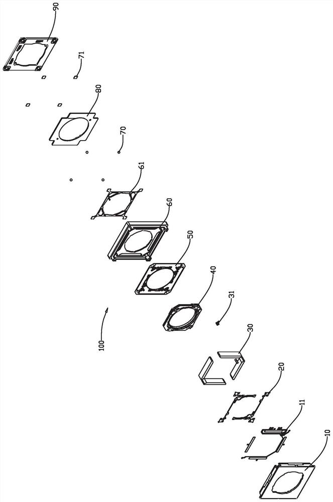
The invention discloses an optical element driving mechanism comprising an upper cover, an upper reed, a magnet group, a carrier, a lower reed, a base, a ball, a bottom circuit board and a base, the carrier and the upper cover are movably connected by the upper reed, the carrier and the base are movably connected by the lower reed, and the bottom circuit board is installed on the base and is fixedly connected with the base. The substrate is used for mounting a chip and is movably connected with the base through a ball, the carrier is provided with a first group of coils, the bottom circuit board is provided with a second group of coils, and the magnet group is fixedly mounted on the upper cover and is matched with the first group of coils to drive the carrier to move and is matched with the second group of coils to drive the substrate to move. According to the invention, optical zooming and optical anti-shake are realized through movement of different parts, and the problem of picture blurring caused by hand shaking in the shooting process is solved.

Description

technical field [0001] The invention relates to the field of optical driving, in particular to an optical element driving mechanism. Background technique [0002] With the development of technology, many electronic devices (such as smart phones or digital cameras) now have the function of taking photos or recording videos. The use of these electronic devices is becoming more and more common, and they are developing towards the direction of convenience and thinner design, so as to provide users with more choices. However, sometimes the photos taken by the current mobile phone will be blurred during the shooting process, that is, the captured picture is not clear enough, and even ghosting or blurring occurs. These reasons, except for occasional out-of-focus (that is, the camera fails to focus normally), are largely due to the slight shake when the scene is exposed. [0003] Generally speaking, such a slight shaking phenomenon often occurs under handheld conditions, which wil...

Claims


Application Information

Patent Timeline
IPC IPC(8): H04N5/232H04N5/225G02B7/04G02B7/09G03B13/34G03B13/36G03B30/00
CPCG02B7/04G02B7/09G03B13/34G03B13/36H04N23/57H04N23/687
Inventor 彭坤林聪刘富泉吕新科其他发明人请求不公开姓名
Owner HENAN HAOZE ELECTRONICS
Why Eureka
Try Eureka