
Screw type interface board

An interface board and interface technology, applied in metal processing, metal processing equipment, hand-held tools, etc., can solve the problem of inconvenient disassembly and assembly of equipment

Inactive Publication Date: 2021-05-11
胡方明
View PDF0 Cites 0 Cited by
  • Summary
  • Abstract
  • Description
  • Claims
  • Application Information

AI Technical Summary

Problems solved by technology

[0003] It is very inconvenient to disassemble and assemble equipment at high places, especially when working at high places that are difficult for personnel to reach

Method used


Image

  • Screw type interface board
  • Screw type interface board
  • Screw type interface board

Examples


Embodiment approach

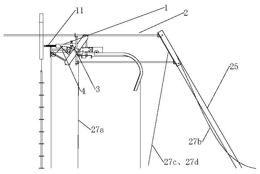
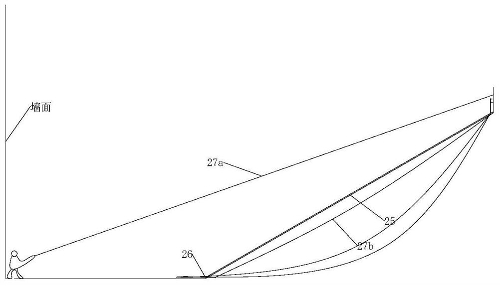
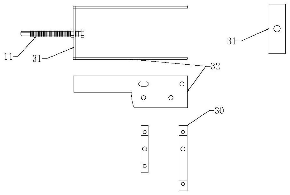
[0005] Technical embodiment of the present invention: an integrated interface board, a base device fixed on the wall, including an interface seat and a fixed seat, or a structural arrangement with the functions of the interface seat and the fixed seat, further, the fixed seat , matched with the fixing piece installed on the integrated interface board, and can be relatively fixed after being installed; the interface seat is matched with the interface piece installed on the integrated interface board, and installed After being inserted, the interface connection can be realized, and the fixing seat and the fixing part are provided with screw structures that match each other. The integrated interface board is characterized in that the main equipment is tiled and installed on the integrated interface board. The integrated interface board is characterized in that it is installed on a bracket on the wall. The fixed seat is characterized in that it includes the function of locating t...


PUM


Abstract

The invention discloses an integrated interface board which is a base device fixed on a wall. The board comprises an interface seat and a fixing seat, or a structural arrangement with the functions of an interface seat and a fixing seat, further, the fixing seat is matched with a fixing piece installed on the integrated interface board, and relative fixation can be achieved after the fixing piece is installed in the integrated interface board; the interface seat is matched with the interface piece installed on the integrated interface board, and interface connection can be realized after the interface piece is installed on the integrated interface board; and the fixing seat and the installed fixing piece are provided with screw structures which are matched with each other. The integrated interface board is characterized in that main equipment is flatly laid on the integrated interface board. The integrated interface board is characterized by being installed on a support on the wall. The fixing seat is characterized by having the function of positioning the direction of the fixing piece which is installed in a matched mode. The interface seat is characterized by having the function of positioning the direction of the interface piece which is inserted in a matched mode. The integrated interface board is characterized in that an unmanned high-place operation device is used for installing an installing-in device or equipment. The unmanned high-place operation device is characterized in that a control tool operation device is supported near a high-place operation point through a supporting rod, a high-place structure where the operation point is located serves as a high-place supporting point, and the unmanned high-place operation device comprises the control tool operation device and the supporting rod. The integrated interface board is characterized by comprising a positioning seat or a structural arrangement with a positioning seat function, and further, the positioning seat is used for positioning an installing device or the installing-in equipment. The integrated interface board is characterized in that a positioning and lifting device is used for installing the installing-in equipment, and further, the positioning and lifting device is installed on the control tool operation device of the unmanned high-place operation device.

Description

[0001] This application is a divisional application of the original invention "Unmanned Disassembly and Assembly Device for High Place Equipment and Its Implementation Method". The original application date was November 9, 2019, and the original application number was 2019110913199. technical field [0002] The invention relates to the installation of high-altitude devices, in particular to the installation of unmanned high-altitude devices. Background technique [0003] It is very inconvenient to disassemble and assemble equipment at high places, especially when working at high places that are difficult for personnel to reach. Contents of the invention [0004] The purpose of the present invention is to design an unmanned high-place disassembly device, which can realize the disassembly and assembly operation of the equipment without reaching the high place. [0005] Technical embodiment of the present invention: an integrated interface board, a base device fixed on the ...

Claims


Application Information

Patent Timeline
Patent Type & Authority Applications(China)
IPC IPC(8): B25B27/00B23P19/00
CPCB23P19/00B25B27/00
Inventor 胡方明
Owner 胡方明
Learn More