Shaft sleeve structure for installing air duct switching device and air duct switching device

A technology for converting devices and air supply ducts, which is applied to washing devices, textiles and papermaking, and household appliances, and can solve the problems of increased structural size, increased number of equipment, and increased occupied space.

Pending Publication Date: 2019-08-09
QINGDAO HAIER DRUM WASHING MACHINE
View PDF0 Cites 0 Cited by
  • Summary
  • Abstract
  • Description
  • Claims
  • Application Information

AI Technical Summary

Problems solved by technology

However, the cooling efficiency of the tap water cooling method is low, the cooling time is long, and it also wastes water resources; although the compressor cooling method has high efficiency and short time, the cost is very expensive
[0004] In addition, the applicant has previously designed a clothes treatment device with two sets of clothes treatment equipment, and the two sets of clothes treatment

Method used


Image

  • Shaft sleeve structure for installing air duct switching device and air duct switching device
  • Shaft sleeve structure for installing air duct switching device and air duct switching device
  • Shaft sleeve structure for installing air duct switching device and air duct switching device

Examples


Embodiment 1

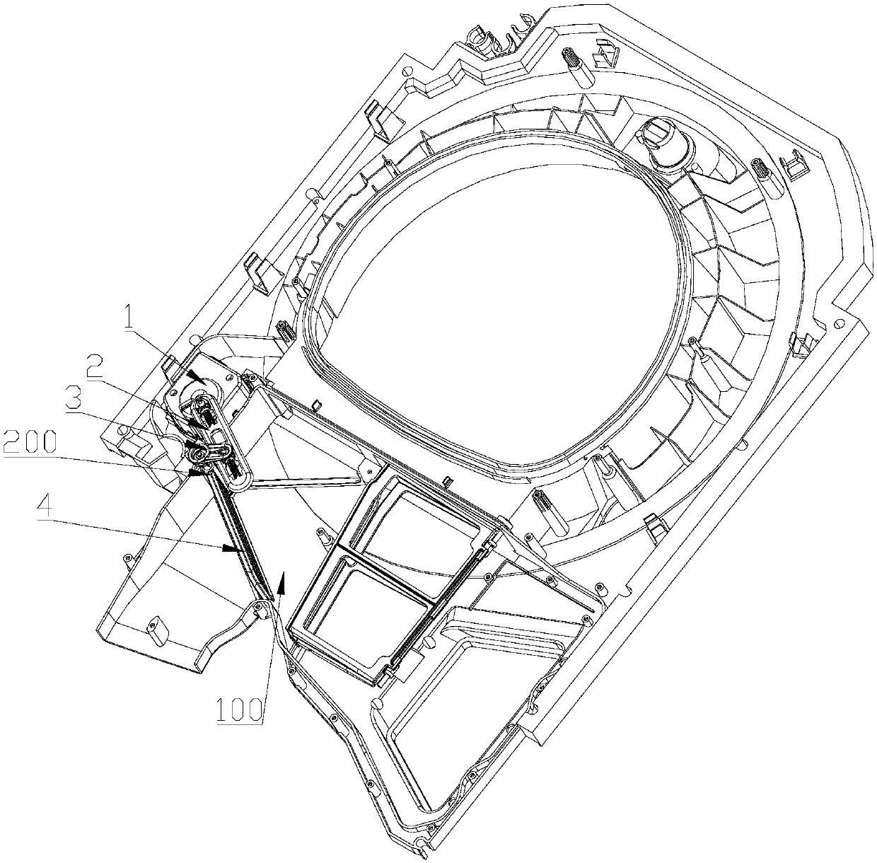
[0060] Such as Figure 1 to Figure 6 As shown, in this embodiment, a shaft sleeve structure for installing the baffle shaft of the air duct conversion device is introduced. One end of the air duct baffle 4 is provided with a baffle shaft 411 extending horizontally to both sides, and the baffle shaft 411 is connected to the The two side walls of the air duct 100 are correspondingly plugged and fixed so that the baffle 411 is relatively rotatably installed in the air duct 100 ; The air duct side wall 101 is provided with a mounting groove 203, and the mounting groove 203 is inserted and fixed with a non-circular bearing sleeve 204, and the bearing sleeve 204 is provided with a baffle shaft 411 for the air duct baffle plate 4 to be plugged in correspondingly. The mounting holes 205.

[0061] A detachable bearing sleeve is provided on the side wall of the air duct to facilitate the detachable replacement of the bearing of the air duct reversing device, and achieve the purpose of ...

Embodiment 2

[0071] Such as Figure 1 to Figure 3 ,Such as Figures 7 to 11 As shown, in this embodiment, an adapter 3 for an air duct conversion device is introduced. The two ends of the adapter 3 are respectively provided with an adapter shaft 31 and an adapter sleeve 32. The adapter shaft 31 and the air duct conversion device The connecting crossbeam 2 of 200 is connected rotatably around the axis, and the adapter sleeve 32 is fixedly connected with the air duct baffle plate 4 of the air duct converting device 200 in a non-rotatable manner.

[0072] By setting the above-mentioned adapter on the air duct conversion device, two different plug-in structures are integrated on the adapter, so as to ensure that the two ends of the adapter are rotatably connected to different components and cannot be rotated relative to each other. connection to achieve the purpose of driving the air duct baffle of the air duct conversion device.

[0073] Such as Figure 8 To such as Figure 10 As shown, i...

Embodiment 3

[0082] Such as image 3 , Figure 7 and Figure 12 to Figure 14As shown, this embodiment introduces an air duct baffle 4 of an air duct conversion device 200, which includes a baffle body 41 and a frame 42, and one side of the baffle body 41 is provided with a baffle shaft extending horizontally to both sides. 411 , the frame wraps the three sides of the baffle body except the baffle shaft 411 . The baffle body 41 and the baffle shaft 411 are integrally arranged, and are driven by the motor 1 to rotate together to realize the opening and closing of the air duct 100 .

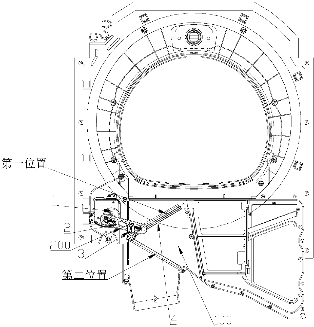
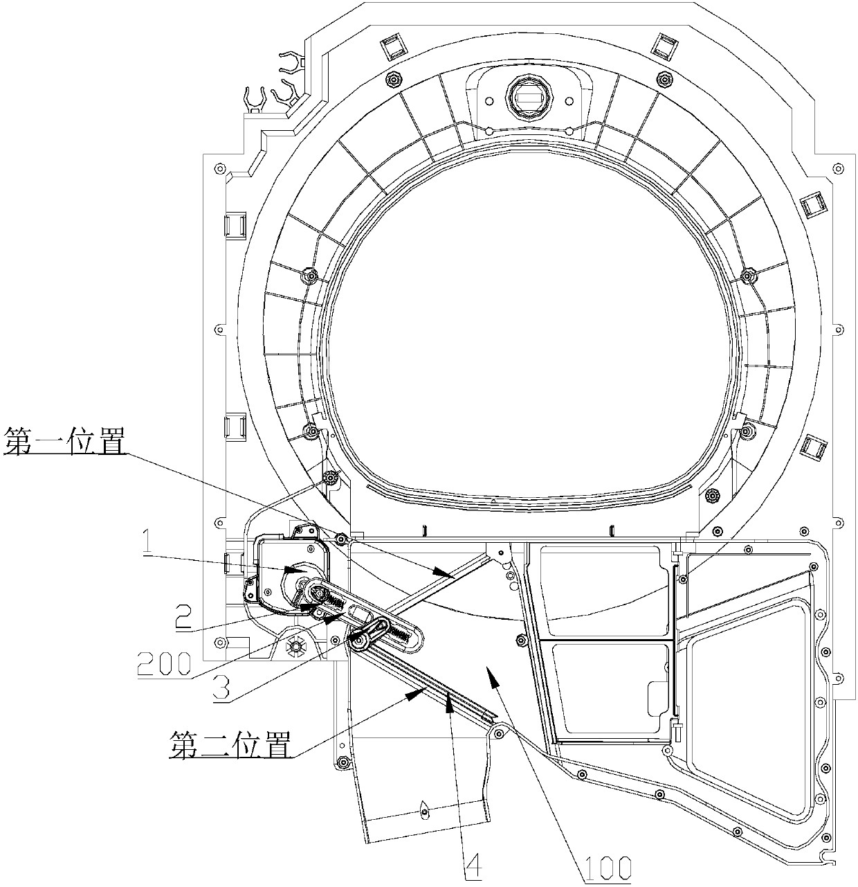
[0083] In this embodiment, the air duct switching device 200 is fixed on the housing through a fixing device, and the air duct baffle 4 switches and moves between the first position and the second position to realize the opening and closing of the air duct 100, and the gas flows through the air duct. Under the interaction between the side wall and the air duct baffle 4, the gas can only flow along the prescri...


PUM


Abstract

The invention discloses a shaft sleeve structure for installing an air duct switching device. An installation groove is formed in the side wall of an air duct, a bearing sleeve with a non-circular periphery is fixedly inserted, connected and fixed in the installation groove, and an installation hole for correspondingly inserting and connecting a baffle shaft of an air duct baffle is formed in thebearing sleeve. The bearing sleeve which is detachably mounted is arranged on the side wall of the air duct, so that a bearing of an air duct reversing device can be detachably replaced, and the purposes of detachably installing and quickly assembling and replacing the bearing sleeve of the baffle shaft are achieved. The invention also discloses the air duct switching device which comprises an airduct baffle plate which is arranged on the air duct and can rotate relatively; the baffle shaft of the air duct baffle is installed in the air duct through the shaft sleeve structure; a motor outputshaft is connected with the air duct baffle through a connecting rod mechanism, so that the air duct baffle is driven to rotate around the shaft through the connecting rod mechanism in the rotating process of the motor output shaft, and the air duct baffle is switched and moved between a first position and a second position.

Description

technical field [0001] The invention belongs to the technical field of household electrical appliances, and in particular relates to an air supply channel conversion device, especially to a shaft sleeve structure for installing the baffle shaft of the air supply channel conversion device, and also relates to an air channel conversion device equipped with the above-mentioned clothes treatment device. Background technique [0002] In the drying mode of the prior art all-in-one drying machine, the condensation drying method is generally used, that is, the closed air duct is used, and the heated dry air heated by the condenser is sent into the drum containing the clothes, and the clothes are dried from the clothes. The humid air that has lost the moisture in the air is sent back to the evaporator for dehumidification. The dehumidified air is heated by the condenser again and sent into the drum. This cycle continuously takes away the moisture on the clothes until the clothes are ...

Claims


Application Information

Patent Timeline
IPC IPC(8): D06F58/20
CPCD06F58/20
Inventor 艾磊磊邢本驸衣少磊赵志伟
Owner QINGDAO HAIER DRUM WASHING MACHINE
Why Eureka
Try Eureka