Slidable transverse bridge direction compression self-resetting damper

A transverse bridge, self-reset technology, applied in the direction of bridges, bridge parts, bridge construction, etc., can solve problems such as structural damage, increase structural strength design, increase design cost, etc., achieve small space, ensure effectiveness, and ensure stability. Effect

Pending Publication Date: 2021-05-11
LUOYANG SUNRUI SPECIAL EQUIP
View PDF0 Cites 0 Cited by
  • Summary
  • Abstract
  • Description
  • Claims
  • Application Information

AI Technical Summary

Problems solved by technology

[0002] Most of the existing dampers are two-way dampers, but the two-way dampers have certain disadvantages. When one end of the two-way damper is connected to a component that can only bear one-way pressure load, the two-way damper at this time will no longer be applicable. In such a scenario, otherwise, the structure will be easily damaged when the component is subjected to tensile load, or in order to prevent the structure from being damaged, it is necessary to increase the structural strength design of the non-acting force direction (unnecessary) in the original structure, which will increase the design cost

Method used


Image

  • Slidable transverse bridge direction compression self-resetting damper
  • Slidable transverse bridge direction compression self-resetting damper
  • Slidable transverse bridge direction compression self-resetting damper

Examples


Embodiment Construction

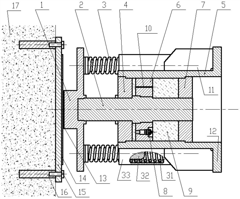
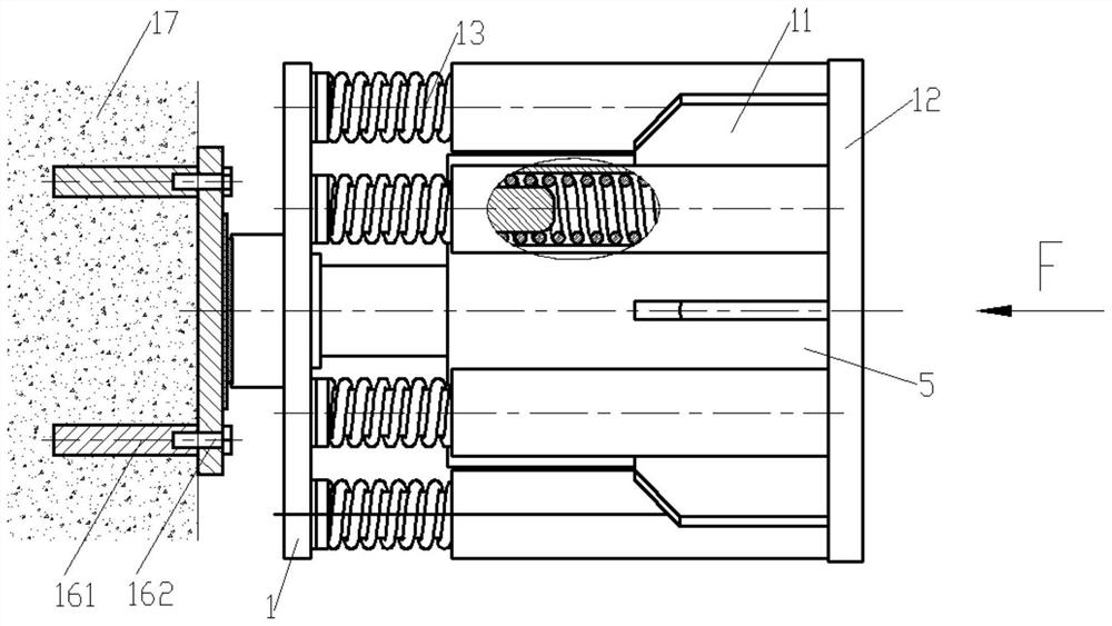
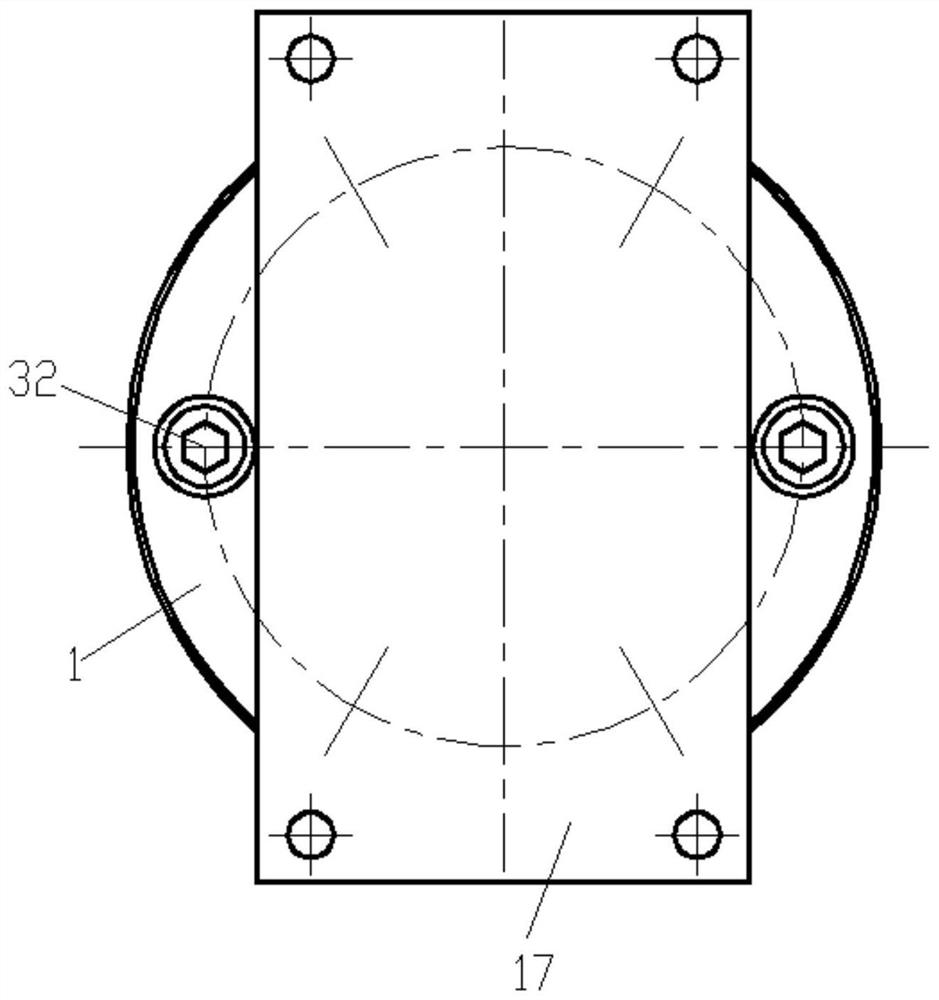
[0033] In order to make the object, technical solution and advantages of the present invention clearer, the present invention will be further described in detail below in conjunction with the accompanying drawings and embodiments. It should be understood that the specific embodiments described here are only used to explain the present invention, not to limit the present invention. In addition, the technical features involved in the various embodiments of the present invention described below can be combined with each other as long as they do not constitute a conflict with each other. It is worth noting that the left and right in this article refer to two opposite directions, which may represent the up and down directions, left and right directions, front and rear directions, oblique directions, etc. in practical applications, and therefore do not fully represent the actual situation.

[0034] In one embodiment of the present invention, as Figure 1-3 As shown, a self-resettin...


PUM


Abstract

The invention discloses a slidable transverse bridge direction compression self-resetting damper which comprises a stress piece, a piston rod, spring assemblies, a left end cover, a cylinder body, a piston, a right end cover and a one-way valve. The left end cover and the right end cover block the left end and the right end of the cylinder body correspondingly, so that the left end cover, the right end cover and the cylinder body define closed space used for containing a damping medium. The piston is arranged in the cylinder body in a sealing and sliding manner and divides the closed space into a left chamber and a right chamber. The piston is provided with a damping hole used for communicating the left chamber with the right chamber and the one-way valve. The damping medium can flow from the left chamber to the right chamber through the one-way valve. The piston rod is arranged on the left end cover and the right end cover in the axis direction of the cylinder body in a sealed and sliding manner. The middle of the piston rod is connected with the piston so as to achieve synchronous movement of the piston and the piston rod. The left end of the piston rod is connected with the stress piece. The multiple spring assemblies are evenly distributed between the stress piece and the cylinder body in the circumferential direction. The slidable transverse bridge direction compression self-resetting damper achieves one-way damping and can also achieve self resetting.

Description

technical field [0001] The invention belongs to the technical field of one-way dampers, and more specifically relates to a self-resetting damper under pressure in the direction of a slidable cross bridge. Background technique [0002] Most of the existing dampers are two-way dampers, but the two-way dampers have certain disadvantages. When one end of the two-way damper is connected to a component that can only bear one-way pressure load, the two-way damper at this time will no longer be applicable. In such a scenario, otherwise, the structure will be easily damaged when the component is subjected to tensile load, or in order to prevent the structure from being damaged, it is necessary to increase the structural strength design of the non-acting force direction (unnecessary) in the original structure, which will increase the design cost . [0003] Especially in the field of bridges, such as the truss girder suspension bridge under the long-span full floating support system, ...

Claims


Application Information

Patent Timeline
Patent Type & Authority Applications(China)
IPC IPC(8): F16F15/067F16F15/023E01D19/00
CPCE01D19/00F16F15/022F16F15/023F16F15/067
Inventor 朱德振梁旭周春王良陈飞彭智浩吕祥
Owner LUOYANG SUNRUI SPECIAL EQUIP
Why Eureka
Try Eureka