Centering elastic coupling

A technology of elastic coupling and elastic parts, applied in the direction of valve details, valve device, rod connection, etc., can solve the problem of excessive output force, easy damage to the thread of the clamp block, and coaxiality between the actuator piston rod and the valve stem Difficult to ask very high questions

Active Publication Date: 2021-05-11
PIPECHINA SOUTH CHINA CO +1
View PDF8 Cites 0 Cited by
  • Summary
  • Abstract
  • Description
  • Claims
  • Application Information

AI Technical Summary

Problems solved by technology

[0002]At present, for straight-stroke valves, most of the actuators and valves are connected by threaded clamping blocks and fastened with screws. This type of connection structure requires valves and actuators to The coaxiality of the output shaft is relatively high, and there are problems that the thread teeth of the clamping block are easily damaged and the installation is difficult
Moreover, when this connection structure is in use, once the valve core exceeds the limit, the output force will all act on the valve seat, which is not suitable for all valves.
[0003] When installing conventional threaded clamps, it is extremely difficult to have the actuator piston rod coaxial with the valve stem. If it is eccentric, it will cause abnormal operation of the actuator or damage to the valve, etc. Fault
The thread clamp connection method is not suitable for displacement control valves such as flat gate valves and regulating valves, because the over-limiting of the valve core caused by poor actuator accuracy may cause the output force to directly act on the valve seat, resulting in excessive output force and damage seat

Method used


Image

  • Centering elastic coupling
  • Centering elastic coupling
  • Centering elastic coupling

Examples


Embodiment Construction

[0024] Unless otherwise specified, the terms herein are to be understood according to the conventional understanding of those of ordinary skill in the relevant art.

[0025] Directions or orientation terms such as axial direction, bottom surface, and top surface described herein are consistent with corresponding directions or orientations in the accompanying drawings. It should be noted that these directions or orientations are used to explain the spatial relative positional relationship of each component or feature of the present invention, and do not have a unique limiting effect on the spatial relative positional relationship of related components or features. Spatial or / and direction / orientation substitutions made on the basis of the technical concept of the present invention are all within the protection scope of the present invention.

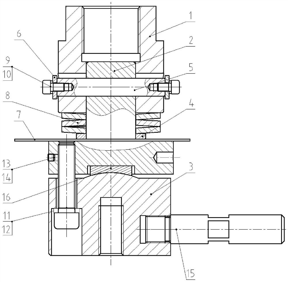
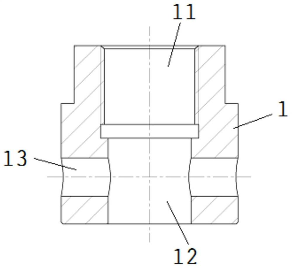
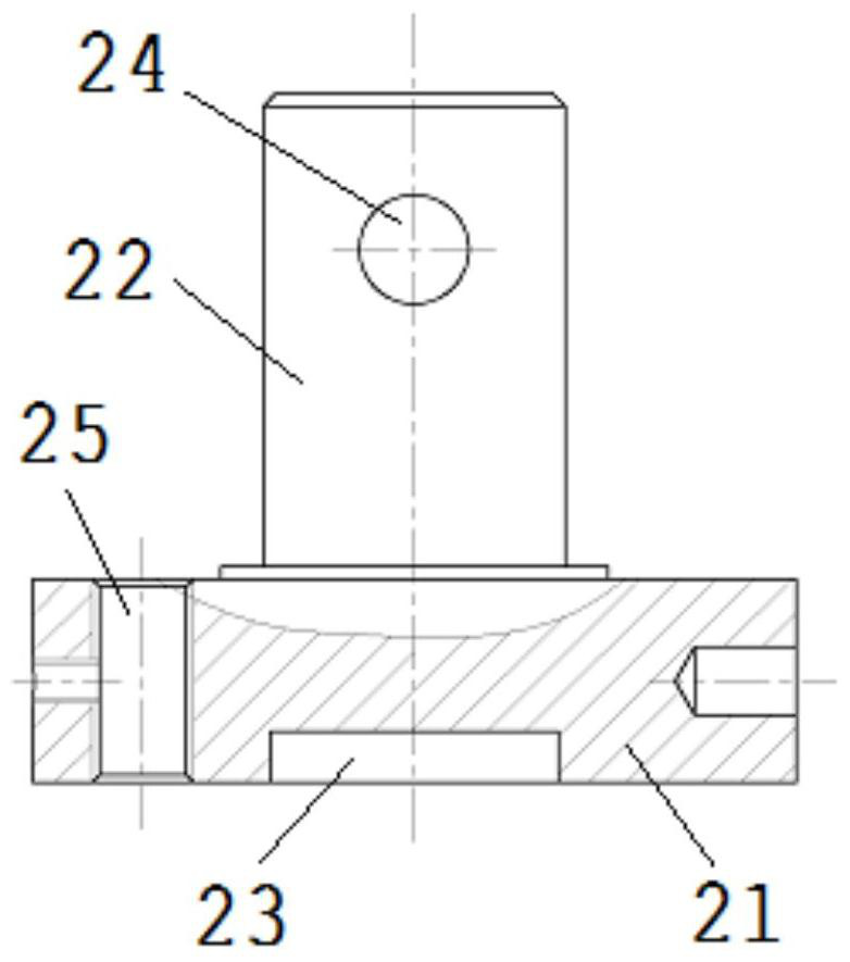
[0026] A specific structure of the center elastic coupling of the present invention is as follows: Figure 1-4 As shown, it includes a ...


PUM


Abstract

The invention discloses a centering elastic coupling. The centering elastic coupling comprises a piston rod sleeve provided with a piston rod mounting hole, a middle base and a valve rod sleeve provided with a valve rod mounting hole, wherein the middle base is connected to the piston rod sleeve, an elastic part is arranged between the middle base and the piston rod sleeve, the middle base is meshed with the valve rod sleeve through a spherical bulge and a spherical groove, the middle base is connected to the valve rod sleeve, and meanwhile the piston rod mounting hole and the valve rod mounting hole are coaxial; the sphere centers of the spherical bulge and the spherical groove are located on the central axis of the piston rod mounting hole and the central axis of the valve rod mounting hole, and the elastic part stretches out and draws back in the axial direction of the piston rod mounting hole and the axial direction of the valve rod mounting hole. The spherical centering structure solves the problem that the coaxiality of the piston rod and the valve rod of an actuator is not high, and is convenient to install and safe to operate; and an elastic connecting structure can ensure the normal operation of the actuator and protect the sealing surface of the valve seat.

Description

technical field [0001] The invention relates to a shaft coupling for valves, in particular to a centering elastic shaft coupling structure, which can be applied to the connection between all straight-stroke valves and actuators, and is also suitable for replacing actuators or valves during maintenance. Background technique [0002] At present, for straight-stroke valves, most of the actuators and valves are connected by threaded clamping blocks and fastened with screws. This type of connection structure requires a high degree of coaxiality between the valve and the output shaft of the actuator, and the thread teeth of the clamping block are prone to problems. Damaged, difficult to install problems. And when this connection structure is in use, once the valve core exceeds the limit, the output force will all act on the valve seat, which is not suitable for all valves. [0003] When installing conventional thread clamps, it is extremely difficult to have the actuator piston r...

Claims


Application Information

Patent Timeline
IPC IPC(8): F16K31/122F16K51/00F16K37/00F16B7/00F16B7/06
CPCF16K31/1221F16K51/00F16K37/0016F16B7/00F16B7/06
Inventor 田中山马锋岗杨昌群蔡婧牛道东郭继璇李育特
Owner PIPECHINA SOUTH CHINA CO
Why Eureka
Try Eureka