Y-shaped flow channel throttling sleeve

A throttling sleeve and flow channel technology, which is applied in the field of regulating valves, can solve the problems of difficult processing of labyrinth disc sleeves, poor throttling effect, short throttling holes, etc., and achieves obvious pressure reduction and throttling effect and long service life. Extend and reduce the effect of pressure relief loss

Active Publication Date: 2021-10-22
WUZHONG ZHONGCHUANG VALVES
View PDF9 Cites 0 Cited by
  • Summary
  • Abstract
  • Description
  • Claims
  • Application Information

AI Technical Summary

Problems solved by technology

Due to the high requirements of the laminations on the curvature and corners of the grooves, the structure is very complicated. After the processing, each throttle plate needs to be welded together in layers. At present, this kind of welding and groove processing equipment is expensive and difficult to achieve, and the processing cost High-end features cause the problem of difficult processing of the labyrinth disc sleeve, and the length of the throttle channel is limited, which cannot effectively play the role of anti-scouring, and the narrow throttle channel makes the flow channel easy to block
There are also inner and outer multi-layer sleeve-type throttling parts. This kind of throttling parts is superimposed by using multi-layer throttling sleeve sleeves. Each layer of throttling sleeves needs to process throttling holes. The difference is 30%, and it plays a throttling role. Each layer needs high-precision coordination, and each layer needs to be welded between layers. This kind of equipment is expensive and takes a long time to process. The yield is low, and the throttling channel is short, and the throttling effect is poor. , general anti-scouring effect

Method used


Image

  • Y-shaped flow channel throttling sleeve
  • Y-shaped flow channel throttling sleeve
  • Y-shaped flow channel throttling sleeve

Examples


Embodiment Construction

[0023] The present invention will be described in detail below in conjunction with the accompanying drawings and specific embodiments, wherein the schematic embodiments and descriptions are only used to explain the present invention, but are not intended to limit the present invention.

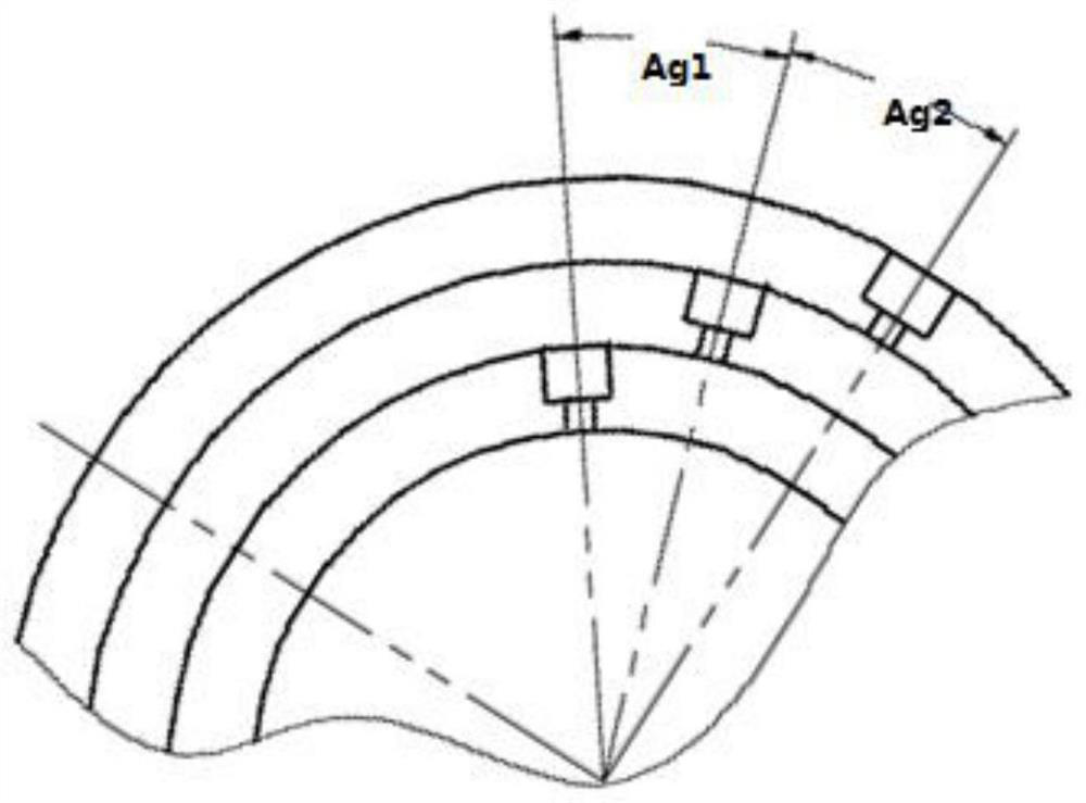
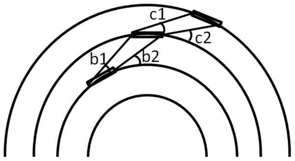
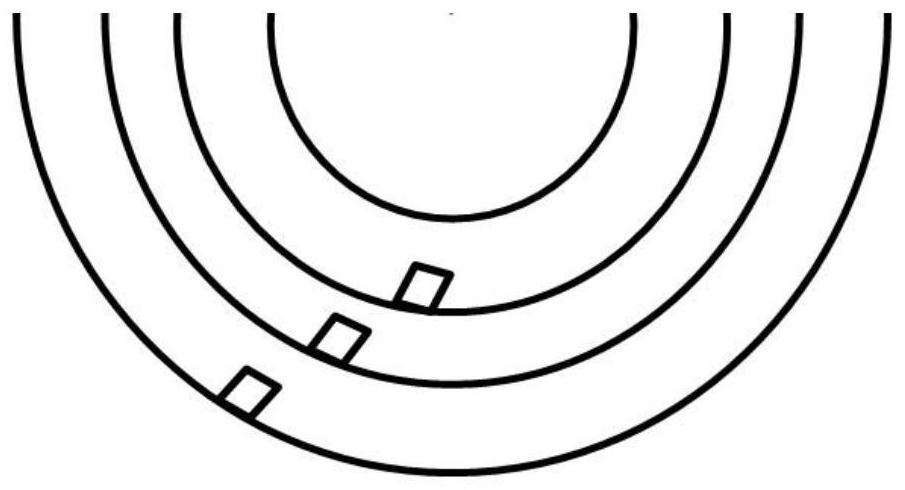
[0024] attached figure 1 As shown, a Y-shaped flow channel throttling sleeve applied in the present invention will be described in detail below. The cylinder body is composed of an inner sleeve, a middle sleeve, and an outer sleeve, which are superimposed and fixedly combined from the outside to the inside. Each of the three-layer Y-shaped flow passage throttling sleeves is in a ring structure, including the inner ring Surface, outer ring surface; uniform annular groove is provided on the inner ring surface, and small flow holes are designed on the outer ring surface, the two form a throttling flow channel from outside to inside, and the medium flow channel is in the form of Y;

[0025] Prefe...


PUM


Abstract

The invention relates to a Y-shaped flow channel throttling sleeve. Three layers of throttling sleeve bodies are used, a groove is machined in an inner hole of each layer of throttling sleeve body, a flow distribution hole is machined in the outer diameter of each layer of throttling sleeve body, and machining can be completed by utilizing common machining equipment. A medium plays a role in throttling through an annular groove, then the purpose of damping and controlling the flow speed of fluid movement is achieved through the flow dividing holes, the flow distribution holes in the outer diameters and the grooves of the inner holes are fully and effectively used for combination, and repeated three-layer throttling and pressure reduction are achieved. The Y-shaped flow channel throttling sleeve is suitable for valve components used in high-pressure-drop liquid, steam and gas emptying occasions such as thermal power, chemical engineering and the like, and has the advantages of cavitation resistance, flash evaporation resistance, low noise, low vibration and the like, machining is easy and convenient, the efficiency is high, and the machining cost is greatly reduced.

Description

【Technical field】 [0001] The invention belongs to the technical field of regulating valves, in particular to a Y-shaped flow path throttling sleeve. 【Background technique】 [0002] Y-type flow channel throttling sleeve is mainly used in small flow throttling valves and temperature reducing and pressure reducing regulating valves. Such valves are widely used in valve components used in high pressure drop liquid, steam and gas venting occasions such as power stations and chemical industries. It has the advantages of anti-cavitation, anti-flash, low noise and low vibration. Existing throttling parts of similar valves are two types: upper and lower disc type and inner and outer multi-layer sleeve type; among them: the upper and lower disc type throttling parts are processed with multiple curved grooves on the upper end surface of each layer of discs, The curved grooves increase the damping of fluid movement and play the role of multi-stage pressure reduction, so that the pressu...

Claims


Application Information

Patent Timeline
Patent Type & Authority Applications(China)
IPC IPC(8): F16K47/08
CPCF16K47/08
Inventor 李新福杨硕王军杨子杨志成李嘉俊丁永辉王浩李天保杨晓娟刘文霞张耀辉穆阳春高阳
Owner WUZHONG ZHONGCHUANG VALVES
Why Eureka
Try Eureka