
Position tracking equipment and method based on optical data and inertial data

A technology of optical data and data, applied in the field of motion capture, can solve problems such as the topological structure should not be too large, collision interference, special-shaped optical rigid bodies can track the number and capacity limit, etc.

Active Publication Date: 2021-05-11
BEIJING NOITOM TECH
View PDF16 Cites 1 Cited by
  • Summary
  • Abstract
  • Description
  • Claims
  • Application Information

AI Technical Summary

Problems solved by technology

This requires that the topological structure cannot be too small, otherwise the lens cannot distinguish each light point on the optical rigid body
But at the same time, it is also required that the topological structure should not be too large, too large will cause mutual collision and interference during grasping and movement
The size of the topology determines the size of the optical rigid body. Within the appropriate size range of the topology, the trackable number of special-shaped optical rigid bodies in the same field will be greatly limited by capacity

Method used


Image

  • Position tracking equipment and method based on optical data and inertial data
  • Position tracking equipment and method based on optical data and inertial data
  • Position tracking equipment and method based on optical data and inertial data

Examples


Embodiment Construction

[0024] In order to more clearly understand the above objects, features and advantages of the present disclosure, the solutions of the present disclosure will be further described below. It should be noted that, in the case of no conflict, the embodiments of the present disclosure and the features in the embodiments can be combined with each other.

[0025] In the following description, many specific details are set forth in order to fully understand the present disclosure, but the present disclosure can also be implemented in other ways than described here; obviously, the embodiments in the description are only some of the embodiments of the present disclosure, and Not all examples.

[0026] Considering that the existing method of using topological structures to mark different optical rigid bodies will greatly limit the number of traceable optical rigid bodies in the same field, the current trackable number of special-shaped optical rigid bodies in the same field is about 23 ...


PUM


Abstract

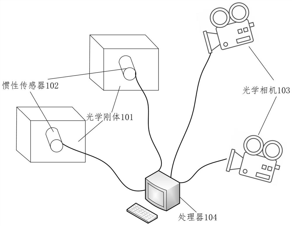
The invention relates to position tracking equipment and a position tracking method based on optical data and inertial data. The position tracking equipment comprises an optical camera, a processor, a plurality of optical rigid bodies of the same topological structure, and inertial sensors fixed in the optical rigid bodies, wherein the optical camera and the inertial sensors are connected with the processor; and different inertial sensors are provided with different identities. The position tracking method comprises the steps of: when the optical rigid bodies rotate to be located at different positions, collecting inertial data through using the inertial sensors; collecting optical data of each optical rigid body through adopting the optical camera; and receiving a plurality of pieces of the optical data and the inertial data through using the processor, determining a matching relationship between the optical rigid bodies and the inertial sensors according to the inertial data and the optical data, and marking the optical rigid bodies having the matching relationship with the inertial sensors by adopting an identity label of the inertial sensor. According to the position tracking equipment and the position tracking method, the accommodating number of optical rigid bodies in the same field can be increased.

Description

technical field [0001] The present disclosure relates to the technical field of motion capture, and in particular to a position tracking device and method based on optical data and inertial data. Background technique [0002] At present, the indoor optical rigid body tracking method based on optical lens mainly relies on the spatial topological structure on the optical rigid body to complete the position and attitude tracking of the optical rigid body; among them, the topological structure is composed of at least three light spots, which can be identified by using different topological structures Different optical rigid bodies. [0003] In the process of identifying and tracking the position and attitude of optical rigid bodies based on topology, when there are multiple optical rigid bodies in the same tracking area, different optical rigid bodies need to be distinguished by different topological structures. This requires that the topological structure should not be too sma...

Claims


Application Information

Patent Timeline
Patent Type & Authority Applications(China)
IPC IPC(8): G01C21/16G01C21/18
CPCG01C21/165G01C21/18
Inventor 何元会周烽胡同杰刘昊扬戴若犁
Owner BEIJING NOITOM TECH
Learn More