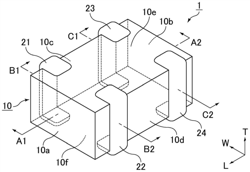
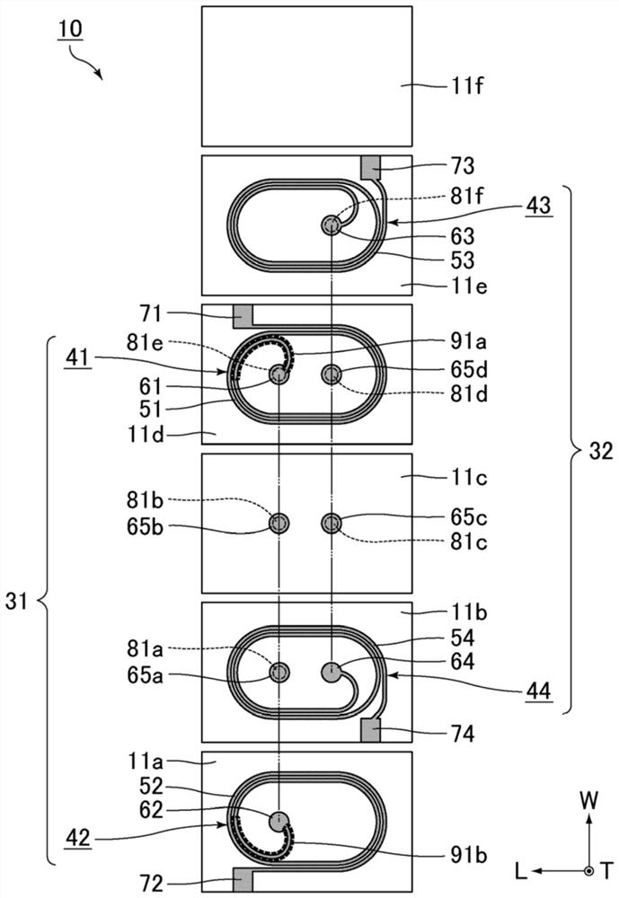
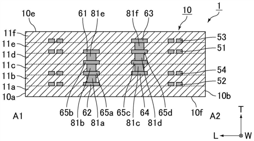
Common mode choke coil

A common mode choke coil and coil technology, which is applied in the direction of transformer/inductor coil/winding/connection, printed inductor, signal inductor without magnetic core, etc., can solve the characteristic impedance deviation of signal line and grounding part , different path lengths, signal waveform passivation, etc., to achieve excellent noise suppression effect

Active Publication Date: 2021-05-11
MURATA MFG CO LTD
View PDF8 Cites 0 Cited by
  • Summary
  • Abstract
  • Description
  • Claims
  • Application Information

AI Technical Summary

Problems solved by technology

However, in such a common mode choke coil, since the path lengths of the two coils are greatly different, there is a possibility that the inductance of the two coils may vary greatly
Therefore, if such a common mode choke coil is incorporated in a circuit, there will be a large deviation in the characteristic impedance between the signal line and the ground (GND) between the lines corresponding to each coil, which may cause a single line to be distorted. Signal Waveform Blunting Concerns
In other words, there is a concern that the noise suppression function of the common mode choke coil is degraded

Method used


Image

  • Common mode choke coil
  • Common mode choke coil
  • Common mode choke coil

Examples


Embodiment 1

[0114] The common mode choke coil of Example 1 was manufactured by the following method.

[0115]

[0116] Weighing K 2 O.B 2 o 3 , SiO 2 、Al 2 o 3 , make them into the prescribed ratio, and mix them in a platinum pot. And the obtained mixture is melt|fused by firing at 1500 degreeC or more and 1600 degreeC or less. Thereafter, the obtained melt is rapidly cooled to produce a glass material.

[0117] Next, by pulverizing the glass material into an average particle size D 50 The glass powder is prepared to be 1 μm or more and 3 μm or less. In addition, as a filler, the average particle diameter D 50 Both are quartz powder and alumina powder of 0.5 μm or more and 2.0 μm or less. Here, the average particle size D 50 It is the particle diameter corresponding to the cumulative percentage of 50% based on volume. Furthermore, a glass ceramic material was prepared by adding quartz powder and alumina powder as fillers to glass powder.

[0118]

[0119] Ceramic slurry i...


PUM

PropertyMeasurementUnit
particle sizeaaaaaaaaaa
thicknessaaaaaaaaaa

Abstract

The present disclosure provides a common mode choke coil that has an excellent noise suppression function. The common mode choke coil that includes an element body formed by stacking a plurality of insulating layers in a height direction; a first coil and a second coil that are built into the element body; a first outer electrode that is provided on a surface of the element body and is electrically connected to one end of the first coil; a second outer electrode that is provided on a surface of the element body at a position that faces the first outer electrode in a width direction that is perpendicular to the height direction and that is electrically connected to another end of the first coil; a third outer electrode that is provided on a surface of the element body and is electrically connected to one end of the second coil; and a fourth outer electrode that is provided on a surface of the element body at a position that faces the third outer electrode in the width direction and that is electrically connected to another end of the second coil. When L1 is an inductance of the first coil and L2 is an inductance of the second coil, 100*the absolute value of L1-L2 / ((L1+L2) / 2)<=5 at 1 GHz.

Description

technical field [0001] The present invention relates to common mode choke coils. Background technique [0002] A common mode choke coil is known as one type of noise filter for electric circuits. For example, Patent Document 1 discloses a common mode choke coil. The common mode choke coil includes: a main body made of an insulator; A coil conductor; a plurality of external electrodes arranged on the surface of the main body; and a plurality of external pads connecting the lead-out part and the external electrode, at the joint where the coil part and the lead-out part are connected, the angle formed by the coil part and the lead-out part is: obtuse angle. [0003] Patent Document 1: International Publication No. 2015 / 029976 [0004] In the common mode choke coil described in Patent Document 1, in order to suppress a decrease in inductance due to partial cancellation of magnetic flux generated by the coil conductors, at the contact point where the coil part and the lead-out...

Claims


Application Information

Patent Timeline
Patent Type & Authority Applications(China)
IPC IPC(8): H01F17/00H01F27/28H01F27/29
CPCH01F17/0013H01F27/2804H01F27/292H01F2017/0093H01F2017/002H01F2027/2809H01F17/03H01F19/04H01F27/32H01F27/33H01F27/29H01F41/041
Inventor 松浦耕平
Owner MURATA MFG CO LTD
Why Eureka
Try Eureka