
Pull riveting type tire repairing nail

A riveting and tire nail technology, which is applied in the field of riveting tire repair nails, can solve problems such as tire bulging, increased use cost, and tire blowout

Pending Publication Date: 2021-05-14
周静
View PDF0 Cites 0 Cited by
  • Summary
  • Abstract
  • Description
  • Claims
  • Application Information

AI Technical Summary

Problems solved by technology

However, the use of these two tire repair methods has certain restrictions, that is, after grinding the damaged part of the tire into a regular through hole, it is generally not recommended to repair the tire if the hole diameter exceeds 6mm, and it is generally not recommended to do tire repair if the sidewall is damaged. Repair, because the effect of tire repair is poor, so it is recommended to replace the tire, which will increase the cost of use and reduce the service life of the tire
The main reason is that the size of the damaged part is large, or the damaged part is located on the sidewall. Even after the tire is repaired, there will be no supporting force at the through hole, and when the tire is driven under the rated air pressure, the tire will be stuck at the repaired part. There will be bulges, and serious tire blowouts may occur
In addition, mushroom nails cannot be used to repair the tire if the slope of the through hole in the damaged part is greater than 15 degrees. The main reason is that if the slope is too large, the sealing between the mushroom nail and the through hole will be affected, resulting in poor tire repair effect.

Method used


Image

  • Pull riveting type tire repairing nail
  • Pull riveting type tire repairing nail
  • Pull riveting type tire repairing nail

Examples


Embodiment 1

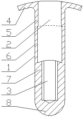
[0050] Such as figure 1 , Figure 4 , Figure 5 , Figure 7 with Figure 10 It can be seen that the riveting type tire repair nail includes a nail body 1, one end of the nail body 1 is provided with a slot A2 along the axial direction of the nail body 1, and the bottom of the slot A2 is connected with a slot B3 , the inner wall of the slot B3 is provided with an internal thread, the inner diameter of the slot A2 is greater than or equal to the major diameter of the internal thread of the slot B3, and one end of the nail body 1 provided with the slot A2 is provided with a flanging outward A4, the part of the nail body 1 corresponding to the slot hole A2, along the direction from the flanging A4 to the slot hole B3, is a reinforcement part 5 and a deformation part 6 in sequence, and the strength of the reinforcement part 5 is greater than that of the deformation part 6 , the part of the nail body 1 corresponding to the slot B3 is the tension part 7, and the flange A4 is an a...

Embodiment 2

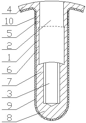
[0054] Such as figure 2 , Figure 4 , Image 6 , Figure 8 with Figure 11 It can be seen that the riveting type tire repair nail includes a nail body 1, one end of the nail body 1 is provided with a slot A2 along the axial direction of the nail body 1, and the bottom of the slot A2 is connected with a slot B3 , the inner wall of the slot B3 is provided with an internal thread, the inner diameter of the slot A2 is greater than or equal to the major diameter of the internal thread of the slot B3, and one end of the nail body 1 provided with the slot A2 is provided with a flanging outward A4, the part of the nail body 1 corresponding to the slot hole A2, along the direction from the flanging A4 to the slot hole B3, is a reinforcement part 5 and a deformation part 6 in sequence, and the strength of the reinforcement part 5 is greater than that of the deformation part 6 , the part of the nail body 1 corresponding to the slot B3 is the tension part 7, and the flange A4 is an a...

Embodiment 3

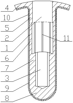
[0057] Such as image 3 , Figure 4 , Image 6 , Figure 9 with Figure 12 It can be seen that the riveting type tire repair nail includes a nail body 1, one end of the nail body 1 is provided with a slot A2 along the axial direction of the nail body 1, and the bottom of the slot A2 is connected with a slot B3 , the inner wall of the slot B3 is provided with an internal thread, the inner diameter of the slot A2 is greater than or equal to the major diameter of the internal thread of the slot B3, and one end of the nail body 1 provided with the slot A2 is provided with a flanging outward A4, the part of the nail body 1 corresponding to the slot hole A2, along the direction from the flanging A4 to the slot hole B3, is a reinforcement part 5 and a deformation part 6 in sequence, and the strength of the reinforcement part 5 is greater than that of the deformation part 6 , the part of the nail body 1 corresponding to the slot B3 is the tension part 7, and the flange A4 is an ar...


PUM


Abstract

The invention discloses a pull riveting type tire repairing nail. A slotted hole A is formed in the end portion of one end of a nail body in the axial direction of the nail body; the bottom of the slotted hole A communicates with a slotted hole B; the inner wall of the slotted hole B is provided with an internal thread; the end, with the slotted hole A, of the nail body is outwards provided with a turnup A; the part, corresponding to the slotted hole A, of the nail body is sequentially provided with a reinforcing part and a deformation part in the direction from the turnup A to the slotted hole B; the part, corresponding to the slotted hole B, of the nail body is a tension part; the turnup A is of a cambered surface structure A attached to the outer side face of a tread bottom rubber layer of a repaired tire; when the tension part is stressed to move towards one side of the turnup A, the middle part of the deformation part bulges outwards to form a turnup B; and the turnup A and the turnup B partially clamp and fix a tire body layer between the tread bottom rubber layer and an airtight layer of the repaired tire. According to the structure of the pull riveting type tire repairing nail, the tire body layer is clamped, sealed and fixed from a through hole in a damaged part of the repaired tire through the turnup A of the nail body and the turnup B formed by the deformation part, so that a tire repairing effect is achieved.

Description

technical field [0001] The invention relates to the technical field of a tire repair device for a tubeless tire, in particular to a riveting type tire repair nail. Background technique [0002] Vacuum tires are tubeless pneumatic tires, also known as "low pressure tires" and "pneumatic tires". Vacuum tires have high elasticity and wear resistance, and have good adhesion and heat dissipation performance. Vacuum tires are increasingly used on bicycles, motorcycles, cars, passenger cars, and trucks. [0003] The tubeless tire is divided into three parts: the carcass, the cord, and the outer tread. The carcass is relatively soft, and the outer tread is more rigid. The cords in the middle play a role in strengthening the strength and shaping of the carcass, and more metal wires are added to improve the elastic performance of the tire. [0004] At present, there are generally two ways to repair tires, one is to directly paste tire repair stickers on the inner liner of the tire, ...

Claims


Application Information

Patent Timeline
IPC IPC(8): B29C73/08B29C73/26B29C73/24
CPCB29C73/08B29C73/24B29C73/26B29C2073/262
Inventor 周静
Owner 周静
Learn More