Heat dissipation device for two-end necking cabin section of underwater sealing cavity

A technology for sealing the cavity and heat dissipation device, which is applied to underwater ships, underwater operation equipment, transportation and packaging, etc., and can solve problems such as difficult installation of heat dissipation devices and poor heat dissipation effect

Inactive Publication Date: 2021-05-14
ZHEJIANG UNIV +1
View PDF6 Cites 0 Cited by
  • Summary
  • Abstract
  • Description
  • Claims
  • Application Information

AI Technical Summary

Problems solved by technology

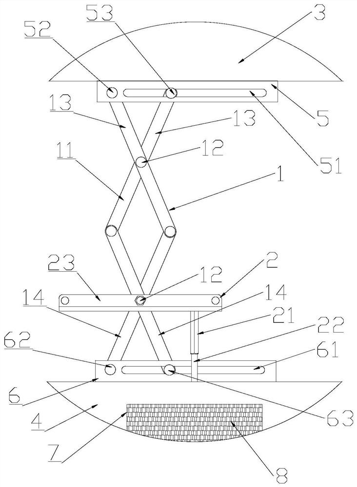
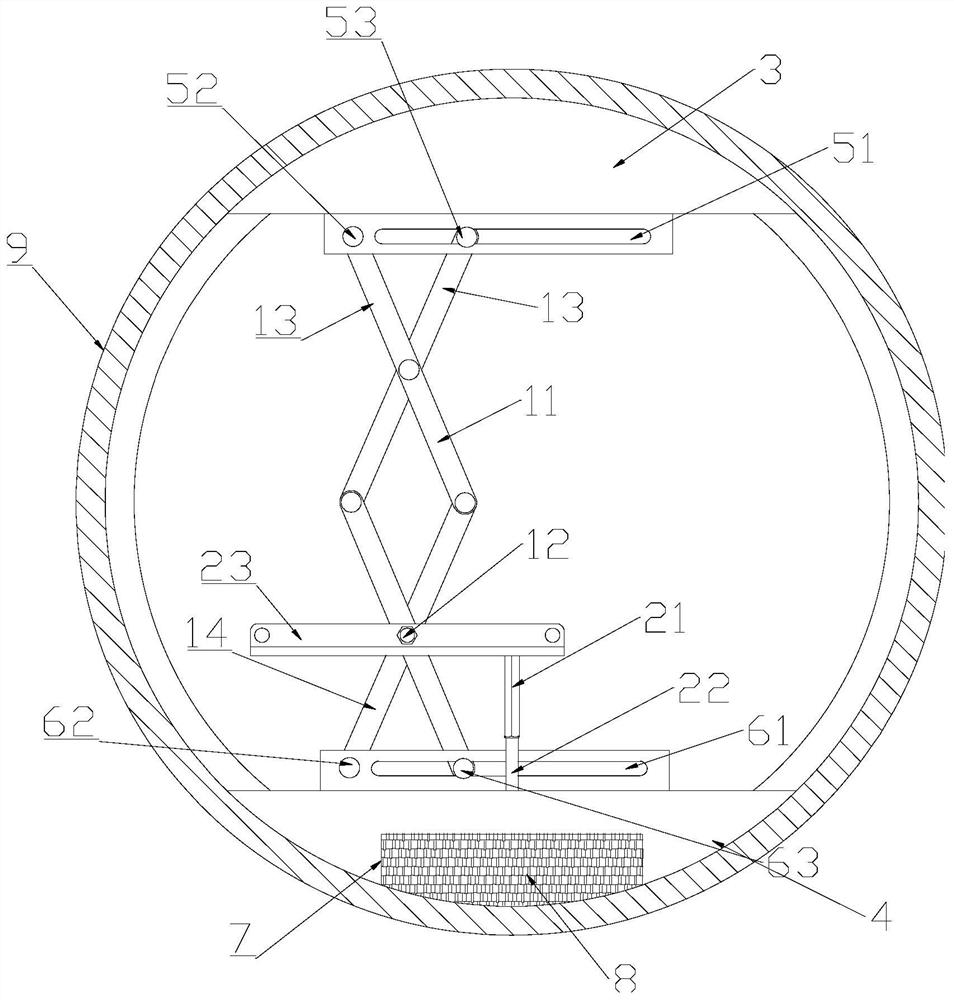
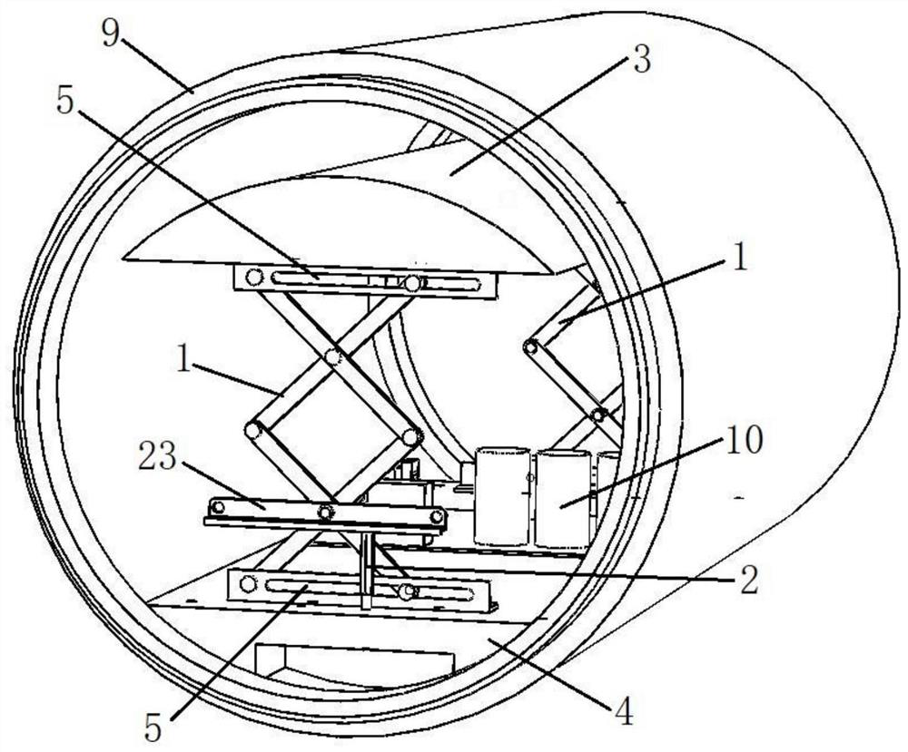
[0006] The invention proposes a heat dissipation device for the shrinkage cabin section at both ends of the underwater sealed cavity, which solves the technical problems of difficult installation and poor heat dissipation effect of the existing heat dissipation device in the shrinkage cabin section at both ends. The structure of the device is simple, In the case of a small entrance size, the wall-attached heat dissipation of the circuit devices inside the underwater cavity can be realized, and the heat dissipation effect can be improved, so as to ensure the normal operation of the circuit devices inside the cabin

Method used


Image

  • Heat dissipation device for two-end necking cabin section of underwater sealing cavity
  • Heat dissipation device for two-end necking cabin section of underwater sealing cavity
  • Heat dissipation device for two-end necking cabin section of underwater sealing cavity

Examples


Embodiment Construction

[0049] In order to make the object, technical solution and advantages of the present invention clearer, the present invention will be described and illustrated below in conjunction with the accompanying drawings and embodiments. It should be understood that the specific embodiments described here are only used to explain the present invention, not to limit the present invention. Based on the embodiments provided by the present invention, all other embodiments obtained by persons of ordinary skill in the art without creative efforts fall within the protection scope of the present invention.

[0050] Obviously, the accompanying drawings in the following description are only some examples or embodiments of the present invention, and those skilled in the art can also apply the present invention to other similar scenarios. In addition, it is also understood that although such development efforts may be complex and lengthy, for those of ordinary skill in the art relevant to the con...


PUM


Abstract

The invention discloses a heat dissipation device for a two-end necking cabin section of an underwater sealing cavity. The heat dissipation device comprises an upper heat conduction block, wherein the upper surface of the upper heat conduction block fits the inner wall of the cabin section; the heat dissipation device further comprises a lower heat conduction block, the lower surface of the lower heat conduction block fits the inner wall of the cabin section, and the lower heat conduction block is arranged below the upper heat conduction block; the heat dissipation device further comprises a rhombic telescopic frame which is supported between the upper heat conduction block and the lower heat conduction block so as to regulate and control the vertical distance between the upper heat conduction block and the lower heat conduction block; the heat dissipation device further comprises a height adjusting piece which is used for adjusting and controlling the height of the rhombic telescopic frame, and comprises a lifting supporting plate fixedly installed on any center hinge shaft of the rhombic telescopic frame, a long screw hole which is formed in the upper surface of the lower heat conduction block and is arranged along the vertical direction, and a supporting rod which is arranged in the vertical direction, the upper end face of the supporting rod abuts against the lower surface of the lifting supporting plate, and a long threaded section is arranged on the lower portion of the supporting rod and is in threaded connection with the long screw hole. The device is simple in structure, wall-attached heat dissipation of circuit devices in the underwater cavity can be achieved under the condition that the size of an inlet is small, and the heat dissipation effect is improved.

Description

technical field [0001] The invention belongs to the technical field of heat dissipation equipment, and in particular relates to a heat dissipation device used for a shrinkage cabin section at both ends of an underwater sealed cavity. Background technique [0002] In scenarios such as deep-sea exploration, dam inspection and maintenance, automatic unmanned underwater vehicles (AUVs) and some other underwater vehicles have great application space. Underwater vehicles such as AUV generally need to be equipped with specific detection equipment, and these equipment usually require power supply. In order to realize underwater operations, the circuit components of the detection equipment need to be loaded in an underwater sealed cavity. The power consumption generated by this type of equipment cannot be ignored. In the case of long-term underwater operation, if the circuit components cannot dissipate heat in time, the performance of the circuit will be affected. When the temperatur...

Claims


Application Information

Patent Timeline
Patent Type & Authority Applications(China)
IPC IPC(8): B63G8/36
CPCB63G8/36
Inventor 段润田李德骏林日林鸣威
Owner ZHEJIANG UNIV
Why Eureka
Try Eureka