Elevator for construction elevator shaft and construction scheme

A technology for construction elevators and elevators, which is applied in the field of elevators, and can solve problems such as frequent loosening or breaking, elevator collapse accidents, and lack of protective measures, so as to reduce the possibility of accidents, improve safety guarantees, and solve safety protection problems Effect

Pending Publication Date: 2021-05-14
ANHUI UNIVERSITY OF TECHNOLOGY
View PDF0 Cites 1 Cited by
  • Summary
  • Abstract
  • Description
  • Claims
  • Application Information

AI Technical Summary

Problems solved by technology

[0002] At present, construction elevators are widely used in construction sites. Since they are installed outdoors at the connection position with the wall, the elevator is greatly affected by the wind during its upward operation. The higher the installation, the greater the wind resistance, the worse the operation stability, and the lower the safety factor; Because the existing elevator has an elevator cage on the left and right sides of the guide rail frame, the lateral tension and vibration of the elevator cage during operation often lead to the loosening of the connecting bolts of the guide rail frame, which in turn leads to the breakage of the bolts and the collapse of the elevator. ;Because the installation and maintenance of the elevator is performed at a high place, there is a lack of reliable protective measures around it, which is difficult and risky; due to insufficient maintenance, the connection bolts of the elevator are loosened or broken from time to time, resulting in frequent accidents of elevator collapse , Elevator collapse casualties have become an increasing trend year by year

Method used


Image

  • Elevator for construction elevator shaft and construction scheme
  • Elevator for construction elevator shaft and construction scheme
  • Elevator for construction elevator shaft and construction scheme

Examples


Embodiment 1

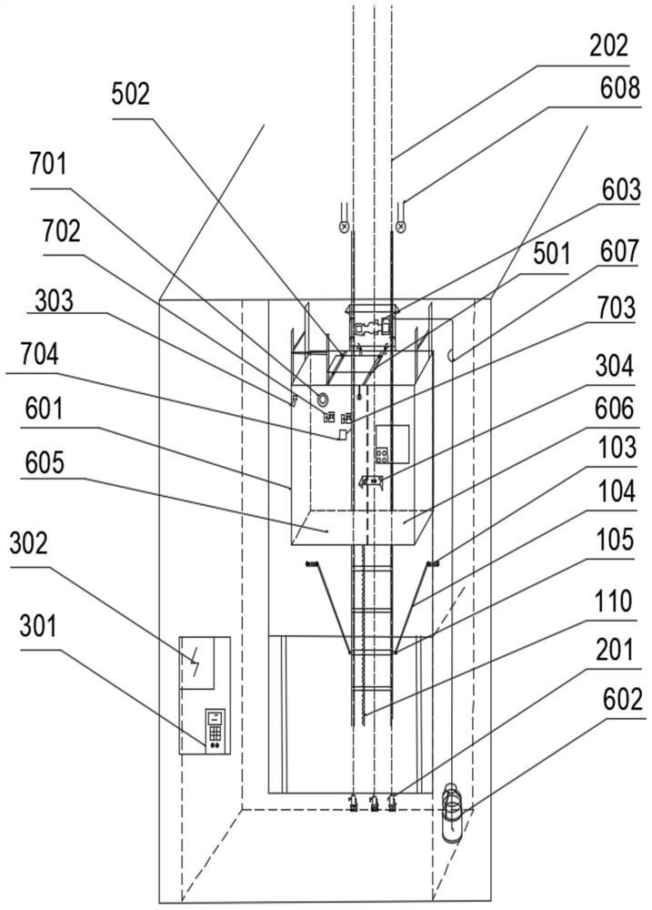
[0033] Such as Figure 1-7 As shown, the present invention is an elevator used for construction of an elevator shaft, including a wall guide rail frame 1, a vertical monitoring device 2, an intelligent door opening device 3, an emergency anti-drop device 4, a guide rail mounting frame 5, a cage running device 6 and a safety device 7;

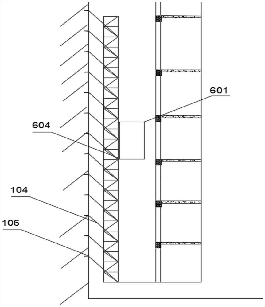
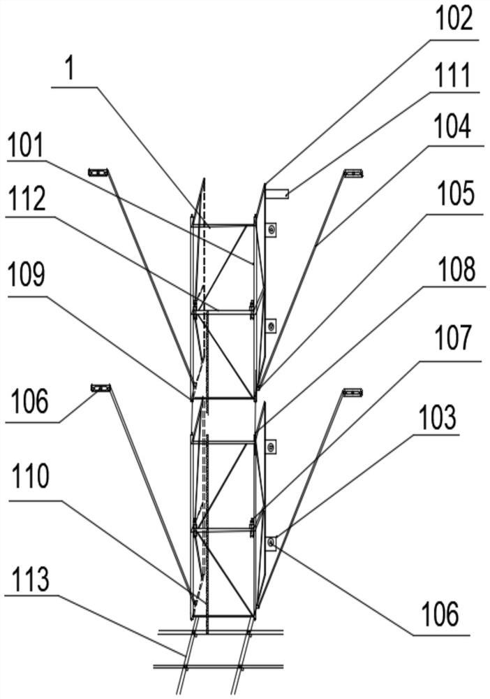
[0034] The guide rail frame attached to the wall 1 includes a cylindrical guide rail 101, a wall frame body 102, a fixed ear plate 103, a diagonal rod 104, a diagonal rod connecting sleeve 105, a fixed bolt 106, a high-strength bolt 107, a rod protruding head 108, and a rod groove 109 , transmission rack 110, height limit baffle 111, limit frame body 112, base 113, wall guide rail frame 1 is fixed on the concrete wall in the construction elevator shaft, and wall guide rail frame 1 has a cylindrical column on the front side The guide rail 101 and the side facing away from the wall frame body 102 with a square tube shape are fixed against the con...

Embodiment 2

[0037] The elevator used for the construction of the elevator shaft, including the guide rail frame attached to the wall 1, the vertical monitoring device 2, the intelligent door opening device 3, the emergency anti-drop device 4, the guide rail mounting frame 5, the cage running device 6 and the safety device 7;

[0038] The guide rail frame attached to the wall 1 includes a cylindrical guide rail 101, a wall frame body 102, a fixed ear plate 103, a diagonal rod 104, a diagonal rod connecting sleeve 105, a fixed bolt 106, a high-strength bolt 107, a rod protruding head 108, and a rod groove 109 , transmission rack 110, height limit baffle 111, limit frame body 112, base 113, wall guide rail frame 1 is fixed on the concrete wall in the construction elevator shaft, and wall guide rail frame 1 has a cylindrical column on the front side The guide rail 101 and the side facing away from the wall frame body 102 with a square tube shape are fixed against the concrete wall body, and fo...

Embodiment 3

[0042] The elevator used for the construction of the elevator shaft and the construction plan, the elevator used for the construction of the elevator shaft, including the guide rail frame attached to the wall 1, the vertical monitoring device 2, the intelligent door opening device 3, the emergency anti-drop device 4, the guide rail mounting frame 5, and the hanging cage Operating device 6 and safety device 7;

[0043] The guide rail frame attached to the wall 1 includes a cylindrical guide rail 101, a wall frame body 102, a fixed ear plate 103, a diagonal rod 104, a diagonal rod connecting sleeve 105, a fixed bolt 106, a high-strength bolt 107, a rod protruding head 108, and a rod groove 109 , transmission rack 110, height limit baffle 111, limit frame body 112, base 113, wall guide rail frame 1 is fixed on the concrete wall in the construction elevator shaft, and wall guide rail frame 1 has a cylindrical column on the front side The guide rail 101 and the side facing away fro...


PUM


Abstract

The invention discloses an elevator for a construction elevator shaft. The elevator for the construction elevator shaft comprises a wall-attached guide rail frame, a vertical monitoring device, an intelligent door opening device, an emergency anti-falling device, a guide rail mounting frame, a cage operation device and a safety device. The wall-attached guide rail frame comprises cylindrical guide rails, a wall-attached frame body, fixing lug plates, inclined pull rods, inclined rod connecting sleeves, fixing bolts, high-strength bolts, rod piece protruding heads, rod piece grooves, transmission racks, a height limiting baffle, limiting frame bodies and a base and is fixed to a concrete wall in the construction elevator shaft. The cylindrical guide rails with a cylindrical shape are arranged on the front side face of the wall-attached guide rail frame, the wall-attached frame body with a square tube shape is arranged on the back side face of the wall-attached guide rail frame, and the wall-attached frame body and the concrete wall body are fixed in a leaning mode. According to the elevator for the construction elevator shaft, the high-strength bolts are adopted for vertical connection and are connected with the concrete wall body in the elevator shaft, stable reliability of the elevator in operation can be ensured, and the safety problems that an outdoor elevator is large in wind load, poor in stability and high in risk are solved.

Description

technical field [0001] The invention relates to the field of elevators, in particular to elevators and construction schemes for construction of elevator shafts. Background technique [0002] At present, construction elevators are widely used in construction sites. Since they are installed outdoors at the connection position with the wall, the elevator is greatly affected by the wind during its upward operation. The higher the installation, the greater the wind resistance, the worse the operation stability, and the lower the safety factor; Because the existing elevator has an elevator cage on the left and right sides of the guide rail frame, the lateral tension and vibration of the elevator cage during operation often lead to the loosening of the connecting bolts of the guide rail frame, which in turn leads to the breakage of the bolts and the collapse of the elevator. ;Because the installation and maintenance of the elevator is performed at a high place, there is a lack of r...

Claims


Application Information

Patent Timeline
IPC IPC(8): B66B7/02B66B5/16B66B5/00B66B11/04B66B11/02B66B1/46B66B1/34
CPCB66B1/3423B66B1/46B66B5/0031B66B5/16B66B7/023B66B11/0233B66B11/0461B66B2201/46
Inventor 陈云钢曹俊仝茂祥张宏俊冯良燕
Owner ANHUI UNIVERSITY OF TECHNOLOGY
Why Eureka
Try Eureka