Vacuum breaker pressure reducing valve with pressure relief function

A technology of vacuum breaking and pressure reducing valve, applied in the field of sanitary ware, can solve the problems of limiting the shape design of the intelligent toilet and low utilization rate of the space of the intelligent toilet, etc.

Active Publication Date: 2021-05-14
JINHUA HONGCHANG ELECTRLCAL EQUIP CO LTD
View PDF10 Cites 0 Cited by
  • Summary
  • Abstract
  • Description
  • Claims
  • Application Information

AI Technical Summary

Problems solved by technology

[0003]As the smart toilet has more and more functions, there are more and more parts on the smart toilet, and it is necessary to install all the parts on the smart toilet For the part connected with the toilet, the pressure reducing valve and the vacuum breaker with pressure relief function are separated in the current market. The installation position of the vacuum breaker with pressure relief function needs to be designed according to the space of the toilet seat, so that the intelligent The space utilization rate on the toilet is relatively low, and it also limits the shape design of the smart toilet

Method used


Image

  • Vacuum breaker pressure reducing valve with pressure relief function
  • Vacuum breaker pressure reducing valve with pressure relief function
  • Vacuum breaker pressure reducing valve with pressure relief function

Examples


Embodiment 1

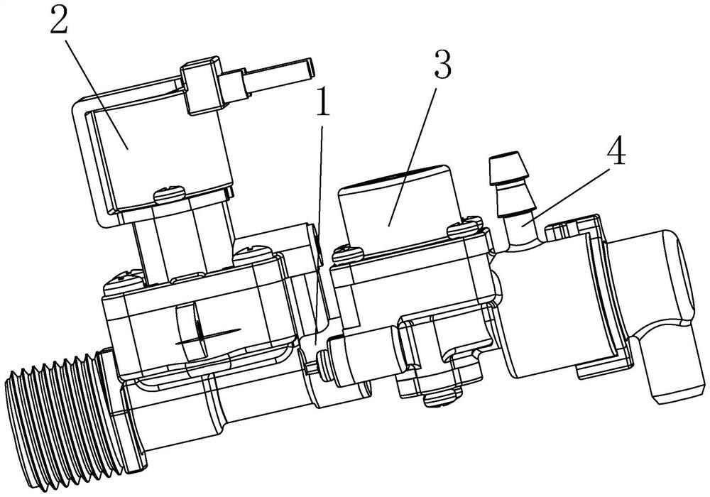
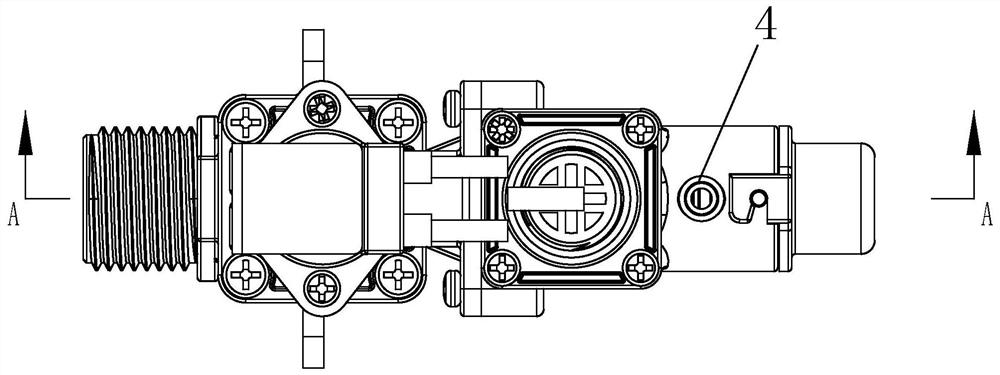
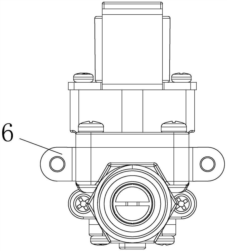
[0027] Such as figure 1 , 2 As shown in , 3 and 4, a vacuum breaker pressure reducing valve with pressure relief function includes a valve body 1, the valve body 1 includes an electromagnetic control mechanism 2 communicating with each other, a pressure relief mechanism 3 for adjusting water pressure and a pressure relief valve. The pressure housing 44, the electromagnetic control mechanism 2 includes a solenoid valve body 7, and the solenoid valve body 7 is sequentially provided with a water inlet 5, a first water inlet chamber 8, a first water outlet chamber 9 and a first water outlet 10, and the first water inlet Between the chamber 8 and the first water outlet chamber 9, an electromagnetic adjustment mechanism for controlling the flow of water is provided. The decompression mechanism 3 includes a decompression valve body 34, and the decompression valve body 34 is provided with a second The water inlet chamber 43, the side of the decompression valve body 34 away from the s...


PUM


Abstract

The invention relates to the field of sanitary ware, in particular to a vacuum breaker pressure reducing valve with a pressure relief function. The vacuum breaker pressure reducing valve with the pressure relief function comprises a valve body, wherein the valve body comprises an electromagnetic control mechanism, a pressure reducing mechanism and a pressure relief shell which communicate with one another, the electromagnetic control mechanism comprises an electromagnetic valve body, the electromagnetic valve body is sequentially provided with a water inlet, a first water inlet cavity, a first water outlet cavity and a first water outlet, and an electromagnetic adjusting mechanism is arranged between the first water inlet cavity and the first water outlet cavity; the pressure reducing mechanism comprises a pressure reducing valve body, a second water inlet cavity communicating with the first water outlet is formed in the pressure reducing valve body, and a second water outlet cavity communicating with the pressure relief shell is formed in one side, away from the second water inlet cavity, of the pressure reducing valve body; a water outlet pipe is connected to the pressure relief shell, a pressure relief cover is arranged on one side, away from the pressure reducing mechanism, of the pressure relief shell in a communicating mode. The vacuum breaker pressure reducing valve with the pressure relief function is high in space utilization rate and convenient to mount.

Description

technical field [0001] The invention relates to the field of sanitary ware, in particular to a vacuum breaker pressure reducing valve with a pressure relief function. Background technique [0002] Smart toilets originated in the United States and are used in medical and elderly care. They were initially equipped with a warm water washing function. With the development of science and technology, smart toilets have more and more functions, which can prevent bacterial infection, prevent hemorrhoids, care for pregnant women, and protect the elderly. In addition to the same advantages as smart toilets, smart toilets also have advantages that smart toilets do not have, that is, they are more convenient to install than smart toilets, cost-effective, and suitable for secondary decoration. [0003] And because the function of intelligent toilet is more and more, the parts and components on the intelligent toilet are also more and more, and parts need to be all installed in the posit...

Claims


Application Information

Patent Timeline
Patent Type & Authority Applications(China)
IPC IPC(8): F16K11/10F16K27/02F16K17/04
CPCF16K11/10F16K27/0263F16K17/0413
Inventor 蔡祖发陆灿梁宁邵巧明楼琳达史春淼
Owner JINHUA HONGCHANG ELECTRLCAL EQUIP CO LTD
Why Eureka
Try Eureka