Sensing networking lamp and lamp set

A technology of induction group and lamps, which is applied to the damage prevention measures of lighting devices, lighting and heating equipment, lighting devices, etc., which can solve the problems of difficult installation and high cost of wire materials, and achieve the reduction of wire cost and the improvement of space utilization. Adjustable range of effects

Pending Publication Date: 2021-05-14
SHENZHEN XINERMEI OPTOELECTRONICS TECH CO LTD
0 Cites 0 Cited by

AI-Extracted Technical Summary

Problems solved by technology

In the related technology, any induction network lamp communicates with other induction network lamps in the same local area network through a wired transmission module, so that other induction network lamps in t...

Method used

Concentrating part 8 is formed with a plurality of concentrating holes 81 along its thickness direction, and each of said concentrating holes 81 is set correspondingly to a plurality of said lamp bodies 22, as shown in Figure 18, each of said concentrating The hole 81 is strip-shaped, and the light-gathering hole 81 has a converging effect on the light emitted by the lamp body 22, so that the lamp body 22 has a better lighting effect on the outside.
It can be understood that an opening is formed in the second protrusion 14, and a boss 611 is formed on the side surface of the second protrusion 61 close to the second protrusion 14, and the boss 611 611 is passed through the opening, and the second protrusion 14 abuts against the surface of the second protrusion 61 to improve the stability of the overall structure.
It can be understood that, as shown in Fig. 14-Fig. 15, since each said focusing hole 81 is set in one-to-one correspondence with each said lamp body 22, said focusing hole 81 emits light to said lamp body 22. The lights play a converging effect, so that the lamp body 22 has a better lighting effect on the outside.
It should be noted that the wireless communication module and the sensor controller 3 can be installed in any one of the first housings 1, and the wireless communication module and the sensor controller 3 can also be installed in In the second housing 6, the wireless communication module and the sensor controller 3 can also be installed in any position except the second housing 6 and the first housing 1, so that the wireless communication module And the installation position of the sensor controller 3 is not limited, so that the space utilization rate is greatly improved.
[0045] Wherein, in order to sense changes in the external environment, the sensor controller 3 includes a control board 31 installed in any one of the first housings...

Abstract

The invention relates to a sensing networking lamp and a lamp set. The sensing networking lamp comprises a plurality of first shells, a lamp piece set, a wireless communication module, and a sensing controller; every two adjacent first shells are rotationally connected with each other; the lamp piece set comprises a plurality of lamp pieces, and the lamp pieces are arranged in the first shells in a one-to-one correspondence mode; the wireless communication module is arranged inside or outside any first shell and used for being in communication connection with other sensing networked lamps in the same local area network; the sensing controller is installed inside or outside any one of the first shells and electrically connected with the lamp piece set and the wireless communication module; the sensing controller is used for sensing external environment changes, generating control signals and controlling the lamp piece set according to the control signals; and the wireless communication module transmits the control signals to other sensing networking lamps in the same local area network. According to the technical schemes, other sensing networking lamps in the same local area network can be controlled at the same time, and the angles of the first shells can be adjusted so that an irradiation range can be adjusted.

Application Domain

Lighting support devicesElectric circuit arrangements +2

Technology Topic

TelecommunicationsLocal area network +3

Image

  • Sensing networking lamp and lamp set
  • Sensing networking lamp and lamp set
  • Sensing networking lamp and lamp set

Examples

  • Experimental program(1)

Example Embodiment

[0037]The present invention will be described in more detail below with reference to the drawings, and the description of the invention is merely illustrative, not limiting. Mutual combination can be combined between each of the different embodiments to form another embodiment not shown in the following description.
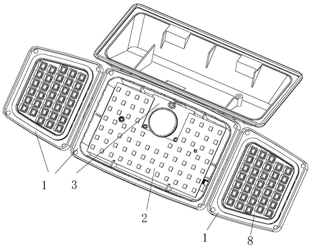
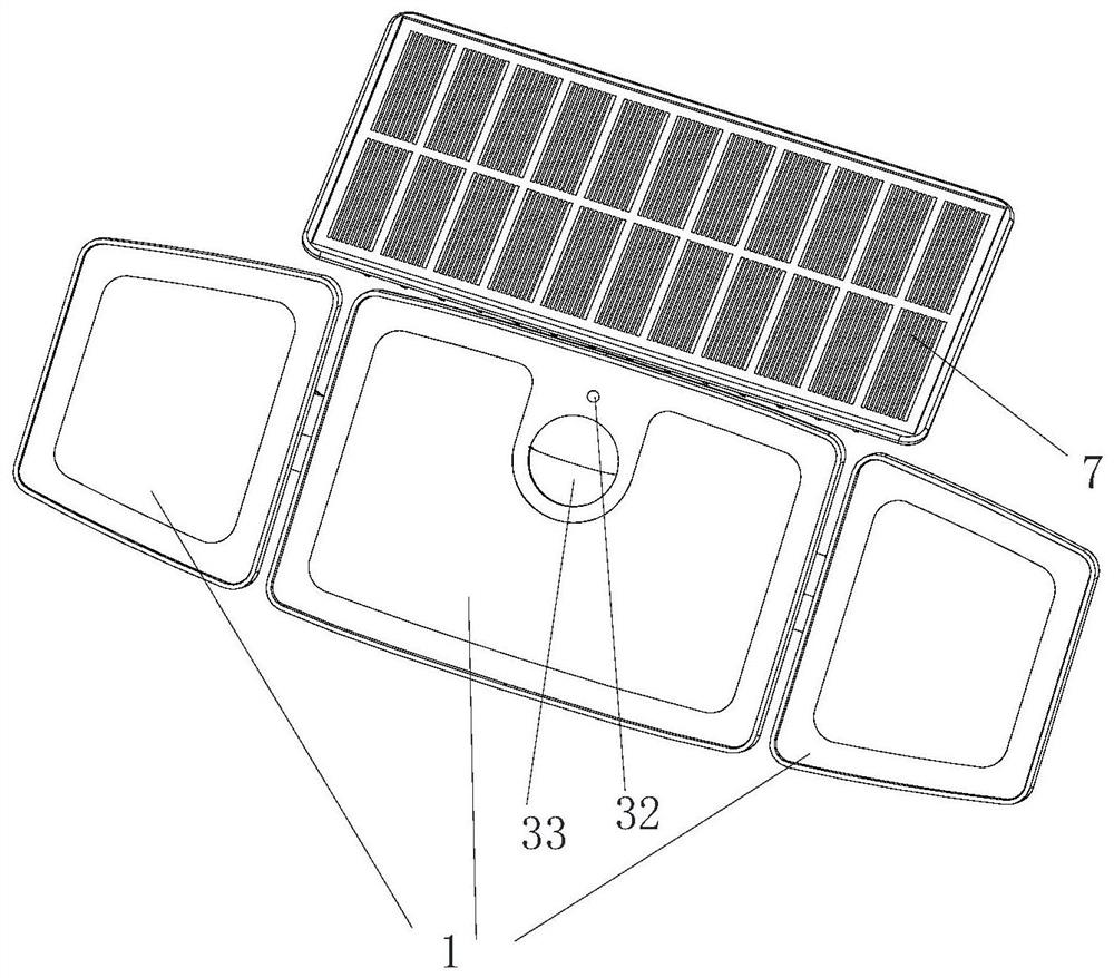
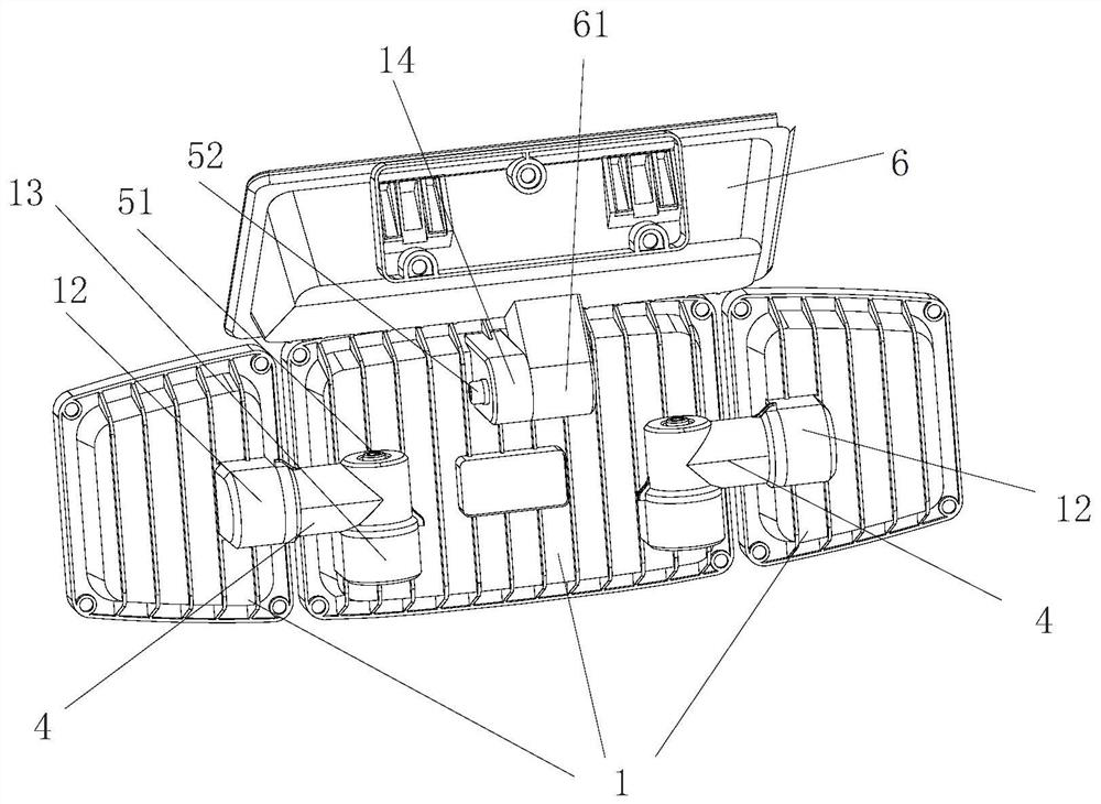
[0038]Seefigure 1 In the embodiment of the present invention, an inductive networking lamp comprising: a first housing 1, a lamp set, a wireless communication module, and a sensor 3.
[0039]A plurality of the first housing 1, there is a rotation connection between the two of the first housings 1; the lamp set includes a plurality of lamps 2, and each of the lamp members 2 corresponds to one or one. Each of the first housing 1; the wireless communication module is disposed within or outside of the first housing 1, for communication with other induction network lights in the same local area network; the sensor 3 is mounted in any of the first housing 1, and is electrically connected to the lamp set and the wireless communication module, wherein the sensor 3 is used to sense the external environmental change and generate control. Signal, the lamp set is controlled according to the control signal, the wireless communication module transmits the control signal to other induction network lights in the same local domain.
[0040]It will be appreciated that the other induction network lights have a wireless communication module and the sensor 3, the appearance, and the structure can be arranged in different forms. In the same local area network, any sensing network lamp is generated after the external environment changes. The control signal can realize the control of other induction network lamps such that the lamp group in other induction network lights achieves the corresponding lighting function, and controls multiple induction network lamps simultaneously in the same larger range. Expand the lighting range.
[0041]When the inductor 3 senses a variation in an external environment, the sensor 3 generates a control signal that transmits the lamp member to control each of the lamps groups. 2 Switches, bright, or other variations, the wireless communication module transmits the control signal to other induction network lights in the same local area network, and other induction network lights receive the control signal to implement lighting function. While expanding the lighting range, since the wireless communication module is employed, the installation of the installation line arrangement is lowered, and the cost of the line material is reduced. Since each of the lamp members 2 corresponds to each of the first housing 1 Inside, and adjacent two of the first housings 1 are rotated, the angle of any of the first housing 1 is adjusted, i.e., the corresponding lamp member 2 angle is adjusted, so that the corresponding the lamp The irradiation angle of the member 2 is adjusted so that the irradiation range composed of the plurality of the lamp members is adjusted, which in turn adjusts the irradiation range of the sensing network lamp, and since the first shell 1 is provided, improved The sensing range of the sensing network lamp lighting is.
[0042]It should be noted that the wireless communication module and the sensor 3 may be mounted in any of the first housing 1, the wireless communication module, and the inductor 3 can also be mounted to the first Inside the second housing 6, the wireless communication module and the inductor 3 may also be mounted to any position except the second housing 6 and the first housing 1, such that wireless communication module and sense The setting position of the device 3 is not limited, thereby greatly improvement of spatial utilization.
[0043]SeeFigure 1-16 As shown, one of the inductive web lamps provided in the first embodiment of the present invention, further comprising: a connector 4, a first rotating member 51, a solar panel 7, a second rotating member 52, and a collecting electrode 8.
[0044]As a preferred embodiment, such asfigure 2 As shown, the first housing 1 is provided with three, which can adjust the angle between the first housing 1 between the left side and the first housing 1 located in the intermediate, or the first shell located on the right side. The angle between the body 1 and the first housing 1 in the middle.
[0045]Among them, in order to sense the external environment change, the sensor 3 includes a control panel 31 mounted in any of the first housing 1, the wireless communication module disposed on the control panel 31, the control board. 31 is electrically connected to the lamp member, the sensor 3 further comprises a sensing member 32 disposed on the control board 31, the sensing member 32 accepts and converts obtaining an environmental change signal, the control panel 31 The control signal is obtained according to the environmental change signal, and it is understood that the sensing member 32 is used to sense changes in the external environment, and transmitted the received signal to the control panel 31, passing through the control panel. 31 Get a control signal, the control signal is transmitted to the lamp assembly, and the wireless communication module will be controlled by each of the lamps sets. The control signal is transmitted to other induction network lamps in the same local area network, and other induction network lights receive the lighting function after the control signal is to enable the lighting range.
[0046]Here, in order to expand the induction range, the sensor 3 also includes a radio frequency unit 33 disposed on the control plate 31, and a support member 11 is formed on the inner wall of the first housing 1 of the control plate 31. The support member 11 is fitted with the side surface of the radius unit 33 in the side of the support member 11, which can be understood, such asFigure 5 As shown, the radical unit 33 interacts with the sensing member 32 for expanding the induction range of the environment, with a better user experience, the support member 11 supports the radius unit 33, so that The sensing member 32 is more stable on the control plate 31, and a reinforcing rib 111 is formed on the inner wall of the first housing 1, and the reinforcing rib 111 is fixed to the support member 11 side, and the strengthening Rib 111 enables the support member 11 to be more stable in the first housing 1.
[0047]Here, in order to achieve a rotation connection between adjacent two first housings 1, one of the first housing 1 is formed on one side surface of the radical unit 33, and is formed with a first convex portion 12. Another first housing 1 adjacent to the first housing 1 is formed on one side surface of the radical unit 33, and the sensing network lighting also includes the first A convex portion 12 is secured to the connecting member 4, and the senseable web luminaire further includes a first rotating member 51 that is fixedly coupled to the first projection 13, the connecting member 4 including the first projection 13 The first connecting portion 41, the first connecting portion 41 rotates to the first rotating member 51.
[0048]It can be understood thatfigure 2 ,Figure 6-8 As shown, when it is necessary to adjust the irradiation range of the sensing network lamp, rotate the first housing 1 or the first housing 1 on the right side, that is, the first convex portion 12 to the connecting member. 4, so that the first connecting portion 41 in the connector 4 is axially rotated about the first rotating member 51, since the first rotating member 51 is fixed to the first protrusions 13 That is, the first connecting portion 41 is rotated about the first projection 13 such that the first housing 1 located on the left and the angle between the intermediate first housing 1 is changed, or in the right The first housing 1 of the side is changed between the angle between the first housing 1 between the intermediates, thereby changing the irradiation range of the sensing network lamp.
[0049]Further, in order to achieve the fixing member 4 and the first convex portion 12, the connecting member 4 further includes a second connecting portion 42 disposed on the side of the first connection portion 41, the second connection. A card tank 421 is formed on one side surface of the first convex portion 12, and the first convex portion 12 is formed with a card member 121 that is engaged with the card slot 421, which is understood. Such asFigure 8 - Figure 10 As shown, a cylindrical hole 122 is formed in the first convex portion 12, which is formed on the wall surface of the cylindrical hole 122, and the chuck 121 is circular, the second connection portion. 42 is a circular column type, and the second connecting portion 42 is formed on a side axis surface of the first convex portion 12, and the second connecting portion 42 is close to the first convex portion. The side axle surface is formed on the side of the side, and the card slot 421 is formed between the extension 422 and the round counter 423, and the card member 121 is fixed to the card slot 421, so that the The connecting member 4 is secured to the first convex portion 12.
[0050]Wherein, each of the lamp members 2 includes a light plate 21 disposed within the first housing 1, and a plurality of lamp body 22 disposed on the lamp plate 21, the induction network lamp. Also included in the first housing 1 and the concentrating electrodes 8 disposed corresponding to the lamp plate 21, the polymeter 8 penetrating a plurality of concentrating holes 81 in the thickness direction thereof, each of which The lamp body 22 is disposed toward each of the aggregated holes 81.
[0051]It can be understood thatFigure 14 - Figure 15 As shown, since each of the aggregate holes 81 correspond to each of the lamp body 22, the concentrating hole 81 is aggregated to the light emitted by the lamp body 22, so that the lamp body 22 is outside. The lighting effect is better.
[0052]In one embodiment, the senseable network luminaire further includes a second housing 6 and a solar panel 7 mounted on the second housing 6, the second housing 6 side and any one. The first housing 1 is rotated, and the other side of the second housing 6 is fixed to the wall, wherein a second convex portion 14 is formed on the first housing 1, the second housing 6. The second projection 61 is formed, and the sensing network luminaire also includes a second rotating member 52 that is fixedly coupled to the second projection 61, the second rotating member 52 away from the second projection 61. One side rotates in the second convex portion 14.
[0053]It can be understood that an opening is formed in the second convex portion 14, and the second projection 61 is formed on one side surface of the second convex portion 14, which is formed with a boss 611, and the boss 611 is inserted. In the opening, the second convex portion 14 is abutted to the surface of the second projection 61 to improve the stability of the overall structure.
[0054]Such asfigure 1 ,figure 2 ,Figure 11 - Figure 13 As shown, the solar panel 7 is used to provide electrical energy to the lamp packet, and when it is necessary to adjust the angle between the solar panel 7 and the first housing 1, in this embodiment, rotation is located The first housing 1, that is, the second convex portion 14 rotates around the second rotating member 52, since the second rotating member 52 is fixed to the second projection 61, ie The second connecting portion 42 is rotated about the second projection 61 such that the angle between the first housing 1 between the intermediate and the solar panel 7 is changed, and the induction web lamp is changed. The irradiation range is further improved, and the second housing 6 is fixed to the wall, so that the sensing network lamp is fixed to the wall, solar panel 7 The angle between the walls is the preset angle. After the installation is completed, the secondary changes are not performed, and the setting stability of the solar panel 7 is improved.
[0055]In other embodiments, the difference from the previous embodiment is that the second housing 6 is rotatably coupled to a plurality of the first housing 1, which is the same as the previous embodiment. Technical effect.
[0056]SeeFigure 17-18As shown, an induced network lighting provided in the second embodiment of the present invention, the difference from the embodiment, and the embodiment, further comprising: a fixed seat.
[0057]The sensor 3 is provided with one side of the first housing 1 toward one side of the first housing 1, which is fixed to the wall from one side of the inductor 3, which can be understood. The fastener 9 is rotated to the first housing 1 in the middle, and the first housing 1 in the intermediate is the same as the second housing 6 rotation of the second housing 6, and the present embodiment is High-pressure market is electrically supplied to the lamp group, which is fixed to the wall, so that the sensing network lamp is fixed to the wall, such asFigure 17 As shown, according to the actual needs, the mounting position of the sensor 3 can be changed so that the spatial utilization is greatly improved.
[0058]The concentrating member 8 is formed through a plurality of concentrating holes 81 along its thickness direction, and each of the concentrating holes 81 are set to a plurality of the lamp body 22, such asFigure 18 As shown, the concentrating holes 81 are stripped, and the concentrating holes 81 are aggregated to the lights emitted by the lamp body 22 such that the lamp 22 is better than the external lighting effect.
[0059]The present invention also provides an induction network lamp set, including a plurality of lamps, the induction network lamp, and a plurality of said senseable network lamps in the same local area network, any of the sensing network The luminaire is induced to generate a control signal after the external environment variation, the control signal enables control of other sensor network lamps, so that other sensor groups in the sensing network lamps achieve corresponding lighting function, in the same more Controlling multiple induction network luminaires in a wide range, expanding the lighting range.
[0060]The above embodiment is only the preferred embodiment of the present invention, and it is not possible to define the scope of the invention, and any non-substantial change and substitutions made in the present invention are in the present invention. The scope of protection is required.

PUM

no PUM

Description & Claims & Application Information

We can also present the details of the Description, Claims and Application information to help users get a comprehensive understanding of the technical details of the patent, such as background art, summary of invention, brief description of drawings, description of embodiments, and other original content. On the other hand, users can also determine the specific scope of protection of the technology through the list of claims; as well as understand the changes in the life cycle of the technology with the presentation of the patent timeline. Login to view more.

Similar technology patents

LED spotlight

ActiveCN109733273APrecise adjustment of lighting angleExtended lighting range
Owner:日照新睿招商发展有限公司

Combined type LED road lamp

InactiveCN101377285AEasy to installExtended lighting range
Owner:江阴市科夏电器有限公司

Lamp

PendingCN113653977AExtended lighting rangeImprove lighting effects
Owner:SHENZHEN OCEANS KING LIGHTING ENG CO LTD +2

Adjustable stage lamp

ActiveCN108954199AExtended lighting rangeEasy to adjust brightness
Owner:江苏泰华消防电气设备有限公司

Swing type fish gathering lamp

PendingCN111306482AExtended lighting rangegood continuity
Owner:SHANGHAI OCEAN UNIV +1

Classification and recommendation of technical efficacy words

  • Reduce installation difficulty
  • Extended lighting range

Hydraulic brake

Owner:焦作瑞塞尔盘式制动器有限公司

Yarn ball spherical curtain wall structure

PendingCN110397196AReduce installation difficultyThe overall structure is stable
Owner:SHENYANG YUANDA ALUMINUM IND GROUP

Protecting cover for street lamp flange base

Owner:常州瑞安普新材料有限公司 +1

Multifunctional machine vision device

ActiveCN103383257Aincrease brightnessExtended lighting range
Owner:MOTIC CHINA GRP CO LTD

Bedside lamp

PendingCN114046467AExtended lighting rangesoft lighting
Owner:深圳市好温馨新材料科技有限公司

Swing type fish gathering lamp

PendingCN111306482AExtended lighting rangegood continuity
Owner:SHANGHAI OCEAN UNIV +1

LED spotlight

ActiveCN109733273APrecise adjustment of lighting angleExtended lighting range
Owner:日照新睿招商发展有限公司

Combined type LED road lamp

InactiveCN101377285AEasy to installExtended lighting range
Owner:江阴市科夏电器有限公司
Why Eureka
Try Eureka