Plate heat exchanger

A technology of plate heat exchangers and heat exchange plates, which is applied in the field of heat exchangers and plate heat exchangers, can solve the problems of insufficient tightness of installation, easy leakage, potential safety hazards of equipment, etc., and achieve the effect of convenient pressing and fixing operation

Inactive Publication Date: 2021-05-14
王建倫
View PDF1 Cites 0 Cited by
  • Summary
  • Abstract
  • Description
  • Claims
  • Application Information

AI Technical Summary

Problems solved by technology

[0004] The purpose of the present invention is to solve the problems in the prior art that the installation is not tight enough, leakage is easy to occur, and there is a certain safety hazard for the use of equipment, and the equipment cannot expand the contact range, so as to better perform heat exchange with low energy consumption and high efficiency operation problems, while a plate heat exchanger proposed

Method used


Image

  • Plate heat exchanger
  • Plate heat exchanger
  • Plate heat exchanger

Examples


Embodiment Construction

[0027] The following will clearly and completely describe the technical solutions in the embodiments of the present invention with reference to the accompanying drawings in the embodiments of the present invention. Obviously, the described embodiments are only some, not all, embodiments of the present invention.

[0028] In describing the present invention, it should be understood that the terms "upper", "lower", "front", "rear", "left", "right", "top", "bottom", "inner", " The orientation or positional relationship indicated by "outside", etc. is based on the orientation or positional relationship shown in the drawings, and is only for the convenience of describing the present invention and simplifying the description, rather than indicating or implying that the referred device or element must have a specific orientation, so as to Specific orientation configurations and operations, therefore, are not to be construed as limitations on the invention.

[0029] refer to Figure ...


PUM


Abstract

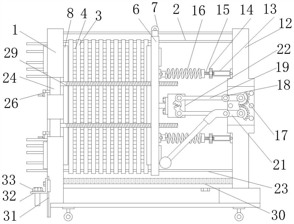
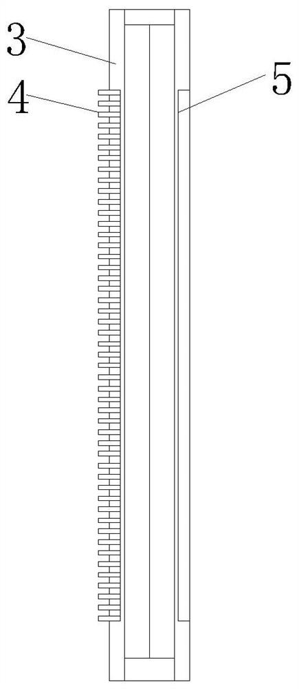
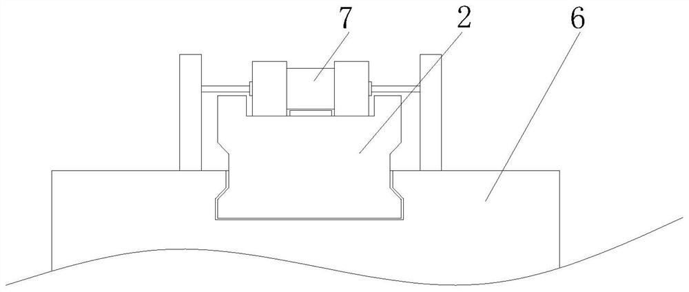
The invention relates to the field of plate heat exchangers, and particularly discloses a plate heat exchanger which comprises a fixed clamping plate, a movable clamping plate and a screw rod, wherein an upper guide rail is arranged on the side of the fixed clamping plate, a heat exchange plate is arranged on the outer side of the upper guide rail, a conduction piece is arranged on the side of the heat exchange plate, and a groove is formed in the other side of the heat exchange plate; and the movable clamping plate is installed on the outer side of the upper guide rail, a guide wheel is arranged on the top of the movable clamping plate, an installation frame is arranged on the inner side of the fixed clamping plate, a protection plate is arranged on the side of the installation frame, a telescopic chain is arranged on the side of the protection plate, a buckle is arranged on the top of the protection plate, a supporting column is arranged at the end of the upper guide rail, a connecting piece is arranged on the side of the supporting column, and a nut is arranged at the end of the connecting piece. The plate heat exchanger is provided with a plurality of installing and pressing structures, so that equipment can be stably installed to the maximum extent, the stability during use is ensured, and the leakage condition of the equipment is avoided.

Description

technical field [0001] The invention relates to a heat exchanger, in particular to a plate heat exchanger, which belongs to the field of plate heat exchangers. Background technique [0002] The plate heat exchanger is a high-efficiency heat exchanger composed of a series of metal sheets with a certain corrugated shape. A thin rectangular channel is formed between the various plates, and heat is exchanged through the plates. The plate heat exchanger is Ideal equipment for liquid-liquid and liquid-vapor heat exchange. [0003] After searching, the Chinese patent authorization number is CN201922010972.X, which discloses a rectangular box plate heat exchanger end plate, including the end plate body, heat exchange plates and pressure plates, and the end plate body is a rectangular box structure , the rear side of the end plate body is provided with an opening, the inside of the end plate body is a hollow structure, several heat exchange plates are placed in the end plate body, t...

Claims


Application Information

Patent Timeline
Patent Type & Authority Applications(China)
IPC IPC(8): F28D9/00F28F9/26F16H37/12
CPCF16H37/124F28D9/00F28F9/26F28F2275/20
Inventor 王建倫冯捷
Owner 王建倫
Why Eureka
Try Eureka