
Steel plate clamping device for U rib plate unit welding and welding equipment

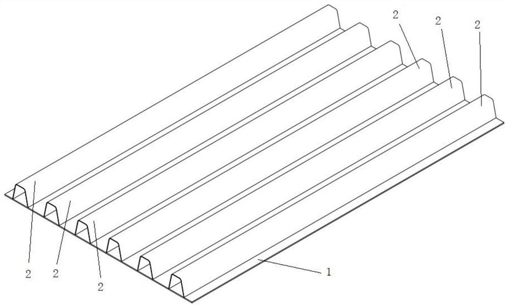
A technology of clamping device and welding equipment, applied in welding equipment, auxiliary welding equipment, welding/cutting auxiliary equipment, etc., which can solve the problem that fixed structures cannot be welded with mobile welding platforms, clamped, and U-rib units cannot be welded, etc. question

Pending Publication Date: 2021-05-18
HUBEI TIANGAO BRIDGE ENG CO LTD +2
View PDF0 Cites 0 Cited by
  • Summary
  • Abstract
  • Description
  • Claims
  • Application Information

AI Technical Summary

Problems solved by technology

This fixed structure cannot be used for the mobile welding platform, and cannot be used for clamping the U-rib unit welding of the moving steel plate

Method used


Image

  • Steel plate clamping device for U rib plate unit welding and welding equipment
  • Steel plate clamping device for U rib plate unit welding and welding equipment
  • Steel plate clamping device for U rib plate unit welding and welding equipment

Examples


Embodiment Construction

[0024] In order to make the object, technical solution and advantages of the present invention clearer, the present invention will be further described in detail below in conjunction with the accompanying drawings and embodiments. It should be understood that the specific embodiments described here are only used to explain the present invention, not to limit the present invention. In addition, the technical features involved in the various embodiments of the present invention described below can be combined with each other as long as they do not constitute a conflict with each other.

[0025] In describing the present invention, it should be understood that the terms "upper", "lower", "front", "rear", "left", "right", "vertical", "horizontal", "transverse", The orientations or positional relationships indicated by "longitudinal", "top", "bottom", "inner", "outer", and "circumferential" are based on the orientations or positional relationships shown in the drawings, and are onl...


PUM


Abstract

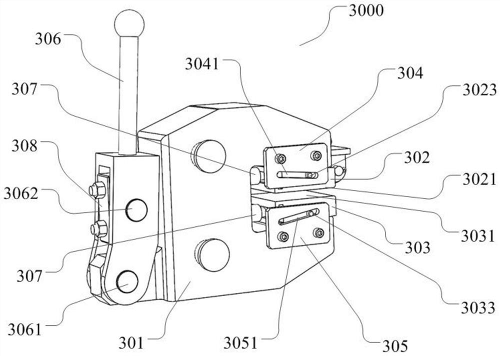
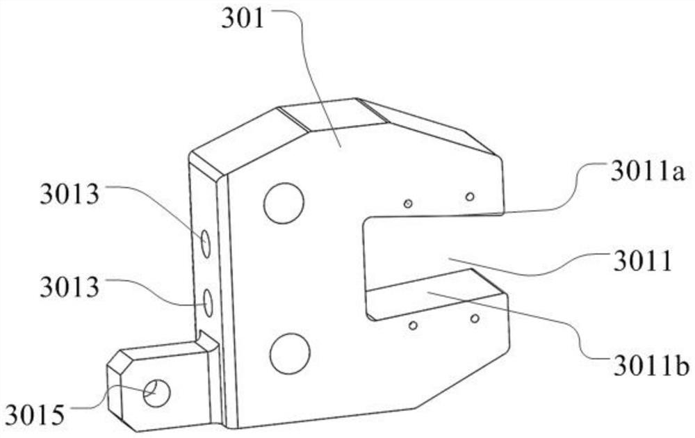
The invention provides a steel plate clamping device for U rib plate unit welding and welding equipment. The steel plate clamping device comprises a fixed seat, an upper clamping block, a lower clamping block, an upper sliding plate and a lower sliding plate, wherein the upper sliding plate and the lower sliding plate are fixed on the fixed seat; the upper clamping block is arranged on the upper sliding plate; the lower clamping block is arranged on the lower sliding plate; the upper clamping block is provided with a lower plane; the lower clamping block is provided with an upper plane; the upper sliding plate is provided with an upper sliding groove; the lower sliding plate is provided with a lower sliding groove; the upper sliding groove and the lower sliding groove are long-strip-shaped grooves which are oppositely arranged; a certain dip angle is arranged between the upper sliding groove and the lower plane of the upper clamping block; a certain dip angle is arranged between the lower sliding groove and the upper plane of the lower clamping block; and the upper clamping block and the lower clamping block can move along the upper sliding groove and the lower sliding groove respectively, so that the distance between the lower plane and the upper plane is adjusted. The steel plate clamping device is reasonable in structure, convenient to assemble, high in clamping force, stable, reliable and capable of being used for a moving platform.

Description

technical field [0001] The invention relates to the field of U-rib unit welding, in particular to a steel plate clamping device and welding equipment for U-rib unit welding. Background technique [0002] In the field of steel structure welding such as bridges and buildings, steel box girder structures are used in large bridges today. Steel box girders are mainly used to provide support and avoid bridge deformation. Steel box girders are generally connected by all-welded roof, bottom, and closed ribs, and the bottom plate and closed ribs form a U-rib unit structure. At present, in practical application, when the steel box girder bottom plate (steel plate) is welded with the steel box girder closed rib (U rib), the welding method of fixing the bottom plate is mostly used. In this welding method, the centering limit of the steel plate is simple, and most of them are direct Fasten it on both sides of the steel plate. This fixed structure cannot be used for the mobile welding p...

Claims


Application Information

Patent Timeline
IPC IPC(8): B23K37/04
CPCB23K37/0435
Inventor 刘建军易伦雄谢瑞杰郑春晓朱腾飞施飞李浪徐图杨毅柴瑞骏胡文喜
Owner HUBEI TIANGAO BRIDGE ENG CO LTD
Learn More