
Protection device for communication equipment

A technology for protective devices and communication equipment, which is applied to container handles, transportation and packaging, containers to prevent mechanical damage, etc. It can solve the problems of cumbersome operation, different appearance and shape, time-consuming and laborious, etc.

Inactive Publication Date: 2021-05-18
刘晓文
View PDF0 Cites 0 Cited by
  • Summary
  • Abstract
  • Description
  • Claims
  • Application Information

AI Technical Summary

Problems solved by technology

[0003] At present, when the communication equipment is transported, most of the communication equipment is put into a protective box, and there is a buffer foam in the protective box, and the communication equipment is fixed by clipping the communication equipment into the buffer foam, so that the communication equipment is placed in the protective box During transportation, it can play a role of buffer protection and improve the safety of communication equipment transportation. However, the appearance and shape of different types of communication equipment are different, which leads to the change of the model of the buffer foam used, which leads to the protection of the protective box. The limitations of loading communication equipment for protection, while using buffer foam to fix the communication equipment, the operation is cumbersome, time-consuming and laborious, and not easy to use

Method used


Image

  • Protection device for communication equipment
  • Protection device for communication equipment
  • Protection device for communication equipment

Examples


Embodiment Construction

[0027] The following will clearly and completely describe the technical solutions in the embodiments of the present invention with reference to the accompanying drawings in the embodiments of the present invention. Obviously, the described embodiments are only some, not all, embodiments of the present invention. Based on the embodiments of the present invention, all other embodiments obtained by persons of ordinary skill in the art without making creative efforts belong to the protection scope of the present invention.

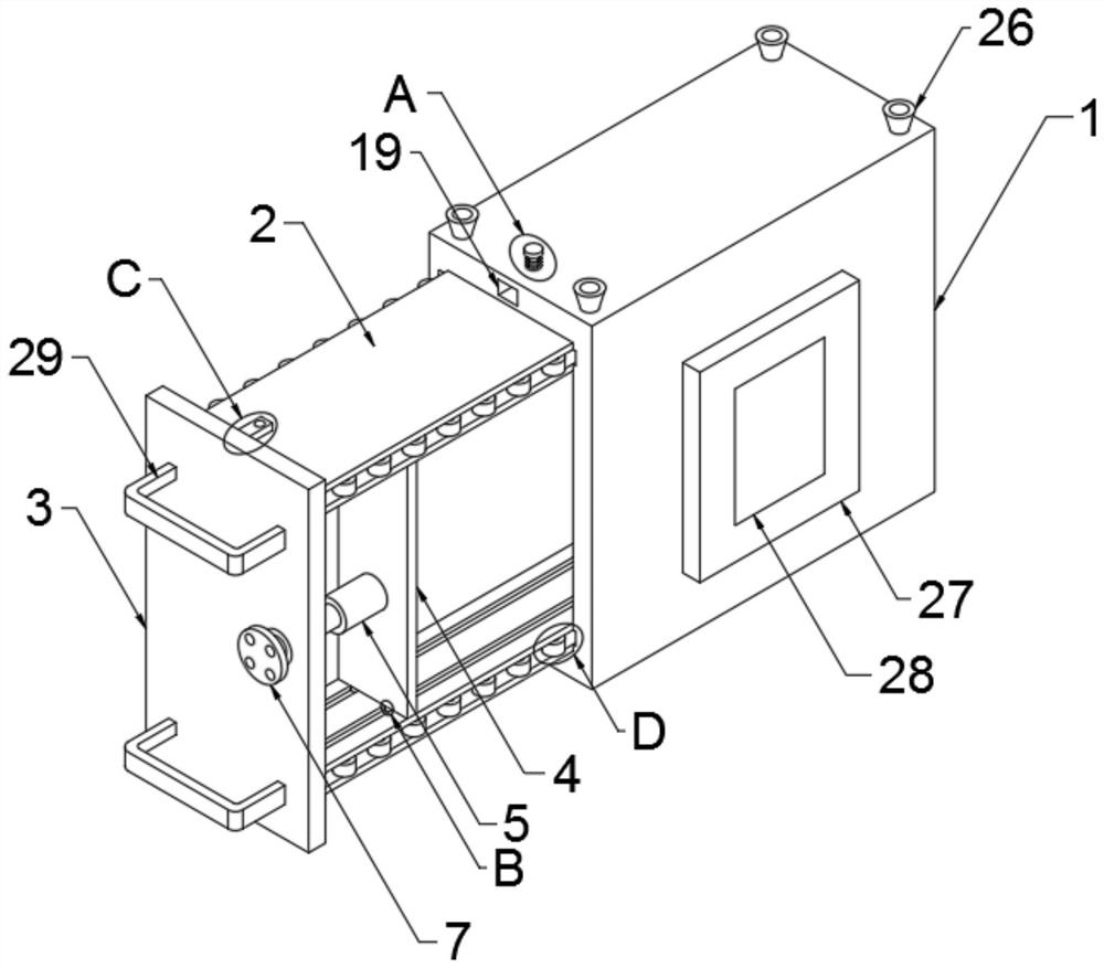
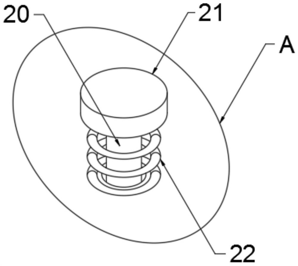
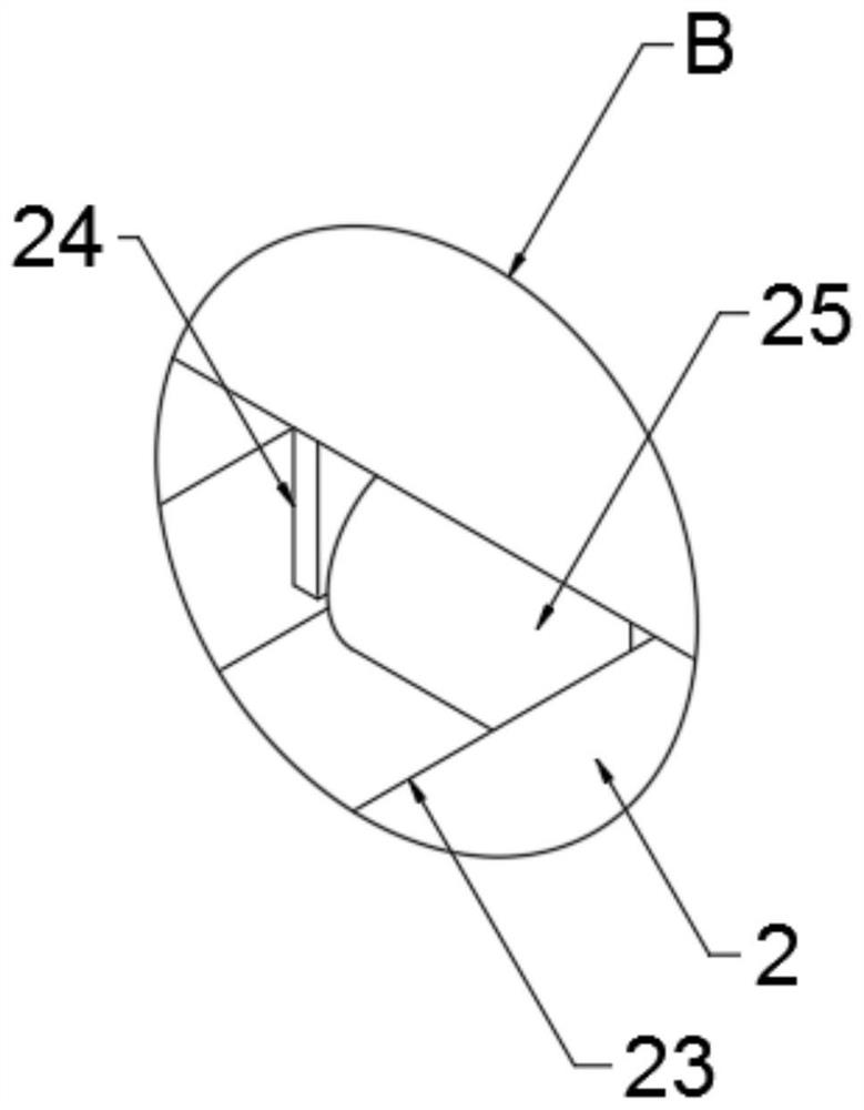
[0028] The present invention provides such Figure 1-7 The protective device for communication equipment shown includes a box body 1, the front of the box body 1 is movably interspersed with a storage box 2 for placing communication equipment, and the front of the storage box 2 is fixedly connected with a protective plate 3, which acts as a The function of limit and connection, the length and width of the protective plate 3 are equal to the width and height of...


PUM


Abstract

The invention discloses a protection device for communication equipment. The protection device comprises a box body, wherein a storage box is movably connected to the obverse side of the box body in a penetrating mode, a protection plate is fixedly connected to the obverse side of the storage box, locking blocks are fixedly connected to the top and the bottom of the reverse side of the protection plate, locking holes are formed in the ends of the two locking blocks, and rectangular grooves are formed in the top and the bottom of the obverse side of the box body. A locking rod is arranged on the top of an inner cavity of each rectangular groove, one end of each locking rod is fixedly connected with a limiting plate, a reset spring is fixedly connected to the bottom end of each limiting plate, each locking rod and the corresponding reset spring are movably arranged in a penetrating mode, and a fixing and protecting mechanism is arranged in an inner cavity of the storage box. According to the protection device for the communication equipment, the arrangement of the box body, the storage box and the protection plate is utilized, cooperates with the usage of the locking blocks, the locking holes, the rectangular grooves, the locking rods, the limiting plates and the reset springs, and cooperates with fixing and protection of the fixing and protecting mechanism to the communication equipment in the storage box, so that the convenience of protection and fixing of the communication equipment is improved, and the operation efficiency is improved.

Description

technical field [0001] The invention relates to the field of protective devices, in particular to a protective device for communication equipment. Background technique [0002] Communication equipment referred to as ICD, limited communication equipment and wireless communication equipment used in industrial control environment, limited communication equipment mainly introduces the solution of serial communication on the industrial site, professional bus communication, industrial Ethernet communication and conversion between various communication protocols Equipment, wireless communication equipment is mainly wireless AP, wireless bridge, wireless network card, wireless lightning arrester, antenna and other equipment. [0003] At present, when the communication equipment is transported, most of the communication equipment is put into a protective box. At the same time, there is a buffer foam in the protective box. The communication equipment is fixed in the buffer foam, so th...

Claims


Application Information

Patent Timeline
IPC IPC(8): B65D25/28B65D25/10B65D25/02B65D81/02
CPCB65D25/02B65D25/10B65D25/28B65D81/02
Inventor 刘晓文
Owner 刘晓文
Learn More