Cable line AC voltage withstand test method and system based on three-phase shunt reactor
A cable line, AC withstand voltage technology, applied in the improvement of basic electrical components, instruments, measurement of electricity and other directions, can solve the problem of test time limit, iron core heating, possibility reduction and so on
Active Publication Date: 2021-05-18
STATE GRID SHAANXI ELECTRIC POWER RES INST +2
View PDF11 Cites 0 Cited by
- Summary
- Abstract
- Description
- Claims
- Application Information
AI Technical Summary
Problems solved by technology
[0006] If a shunt reactor is used instead of the test reactor, no matter whether the single-phase or two-phase or three-phase parallel connection of the reactor is used in the test, due to the existence of the air gap on the main column, the two side colum
Method used
View moreImage
Smart ImageViewing Examples
Examples
 PUM
| Property | Measurement | Unit |
|---|---|---|
| Resonant frequency | aaaaa | aaaaa |
Abstract
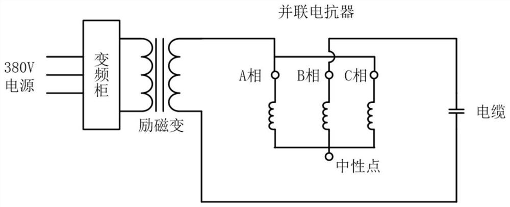
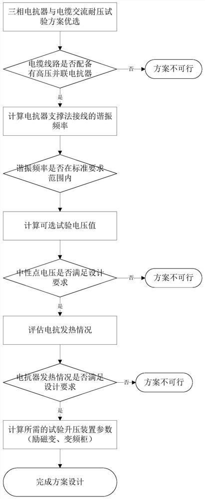
The invention discloses a cable line AC voltage withstand test method and system based on a three-phase shunt reactor. The method comprises the following steps that: a to-be-tested cable line is equipped with a three-phase shunt reactor, and the three-phase shunt reactor is used for compensating the ground capacitance current of the cable line; and in a cable line AC voltage withstand test adopting a series resonance mode, the three-phase shunt reactor replaces a test reactor to carry out an AC voltage withstand test on the cable line. The two phases of the three-phase shunt reactor are short-circuited and then connected with the high-voltage side of the secondary winding of an excitation transformer, the other phase of the three-phase shunt reactor is connected with a sleeve, and the neutral point of the three-phase shunt reactor is kept suspended from the ground. According to the invention, the magnetic flux in the two side columns of the shunt reactor can be greatly reduced, and the heat release condition of the iron core is reduced; and higher test voltage and longer test time are allowed to be adopted, and the feasibility of replacing a test reactor with a three-phase shunt reactor can be greatly improved.
Description
technical field [0001] The invention belongs to the technical field of voltage withstand test of cable lines, and in particular relates to an AC withstand voltage test method and system of cable lines based on three-phase shunt reactors. Background technique [0002] With the development of urban economy, urban land resources are becoming increasingly tense, and traditional high-voltage overhead lines have been difficult to meet the needs of current urban development. Power cables, with their small footprint, safety and reliability, account for an increasing proportion of urban power transmission systems. Due to the possible manufacturing defects of the cable, the processing defects of the cable joints, and the interference of other factors received during installation and operation, problems such as failures and short circuits may occur. Therefore, it is very necessary to use the AC withstand voltage test to assess the insulation level of the cable before putting it into op...
Claims
Login to View More Application Information
Patent Timeline
 IPC IPC(8): G01R31/12G01R1/20
CPCG01R31/1272G01R1/20
Inventor 王荆韩彦华盛勇吴经锋黄国强刘强师一卿蒲路琚泽立丁彬江涛李旭万康红
Owner STATE GRID SHAANXI ELECTRIC POWER RES INST
Features
- R&D
- Intellectual Property
- Life Sciences
- Materials
- Tech Scout
- Unparalleled Data Quality
- Higher Quality Content
- 60% Fewer Hallucinations
Learn More Browse by: Latest US Patents, China's latest patents, Technical Efficacy Thesaurus, Application Domain, Technology Topic, Popular Technical Reports.
© 2025 PatSnap. All rights reserved.Legal|Privacy policy|Modern Slavery Act Transparency Statement|Sitemap|About US| Contact US: help@patsnap.com


