A cloud platform for a range-measuring aircraft and a control method for the platform

A technology of aircraft and gimbal, which is applied in the direction of control, instrument, and measurement device using feedback, which can solve the problems of poor reliability, small driving force, and difficulty in ensuring volume.

Active Publication Date: 2021-08-10
北京天创凯睿科技有限公司
View PDF3 Cites 0 Cited by
  • Summary
  • Abstract
  • Description
  • Claims
  • Application Information

AI Technical Summary

Problems solved by technology

[0004] The purpose of the present invention is to provide a pan-tilt and a method of using the pan-tilt for ranging and taking pictures of the aircraft, so as to solve the problem that the multi-axis pan-tilt in the prior art has small driving force and poor reliability, and it is difficult to ensure a large volume. , The problem of the stability of the position of the heavy laser range finder

Method used


Image

  • A cloud platform for a range-measuring aircraft and a control method for the platform
  • A cloud platform for a range-measuring aircraft and a control method for the platform
  • A cloud platform for a range-measuring aircraft and a control method for the platform

Examples


Embodiment 1

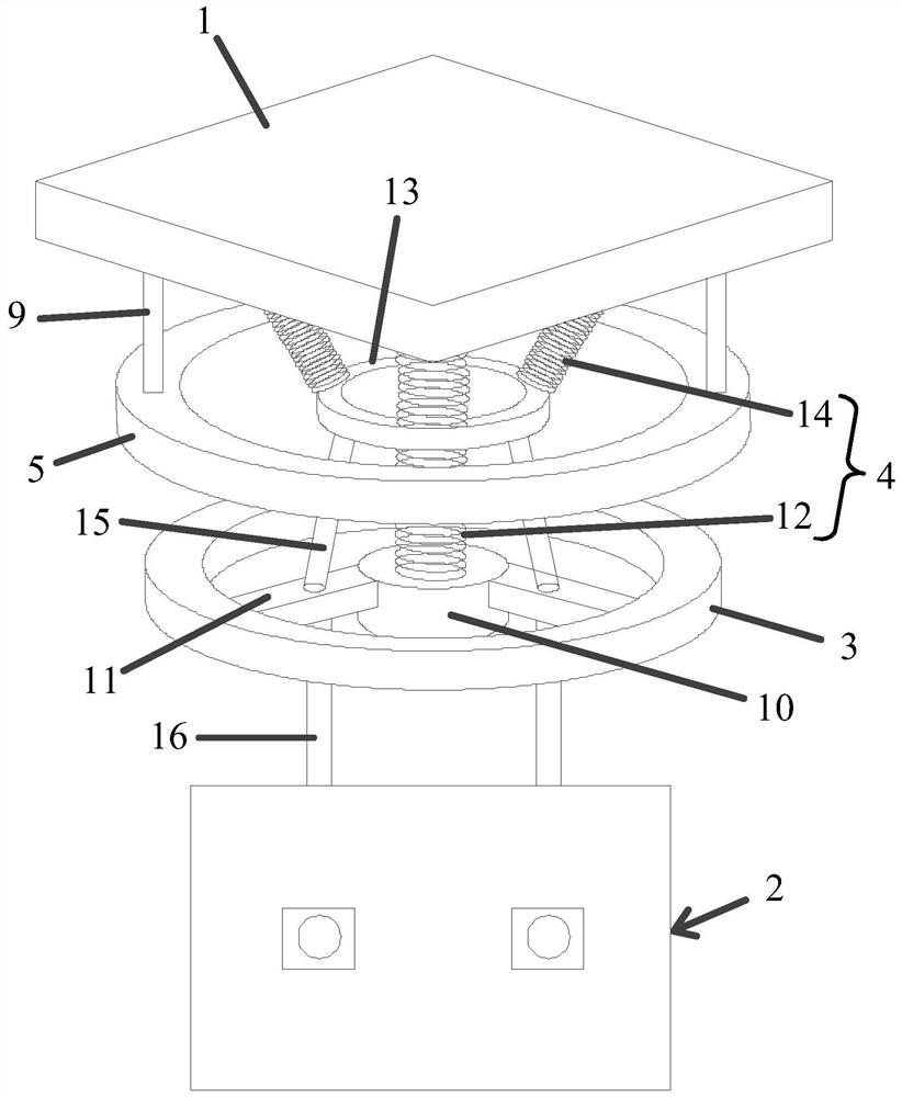
[0049] A gimbal for ranging aircraft is recorded, such as figure 1 shown, which includes:

[0050] The fixed platform includes: a connecting plate 1 connected to the aircraft, and a first annular support frame 3 for fixing the range finder 2, the connecting plate 1 and the first annular support frame 3 are connected by an elastic element 4; The first annular support frame 3 is wound with a first energized coil in the circumferential direction, and the first energized coil is connected with the first power supply line;

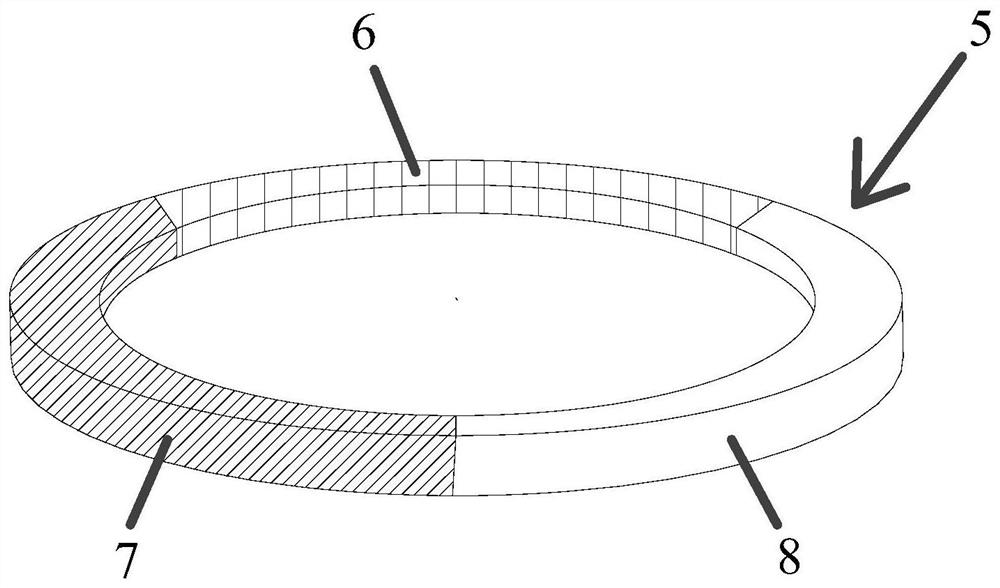
[0051] The magnetic force generating mechanism includes: a second annular support frame 5 adapted to the shape of the first annular support frame 3, and the second annular support frame 5 is wound with at least three mutually independent second The energized coil, the second energized coil includes: a first coil 6, a second coil 7, and a third coil 8 arranged sequentially in the circumferential direction of the second annular support frame 5; the first coil 6,...

Embodiment 2

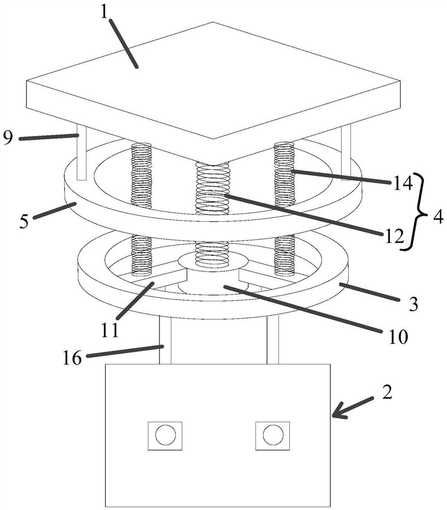
[0063] A gimbal for ranging aircraft is recorded, such as figure 2 shown, which includes:

[0064] The fixed platform includes: a connecting plate 1 connected to the aircraft, and a first annular support frame 3 for fixing the range finder 2, the connecting plate 1 and the first annular support frame 3 are connected by an elastic element 4; The first annular support frame 3 is wound with a first energized coil in the circumferential direction, and the first energized coil is connected with the first power supply line;

[0065] The magnetic force generating mechanism includes: a second annular support frame 5 adapted to the shape of the first annular support frame 3, and the second annular support frame 5 is wound with at least three mutually independent second The energized coil, the second energized coil includes: a first coil 6, a second coil 7, and a third coil 8 arranged sequentially in the circumferential direction of the second annular support frame 5; the first coil 6...


PUM


Abstract

A cloud platform for a distance-measuring aircraft and a control method for the platform, the cloud platform for a distance-measuring aircraft includes: a fixed platform, including: a connecting plate connected with the aircraft, and a first ring for fixing the rangefinder The supporting frame, the connecting plate and the first annular supporting frame are connected by elastic elements; the first annular supporting frame is a magnetic element; the magnetic force generating mechanism includes: a second annular supporting frame, and at least Three mutually independent second energized coils; a gyroscope, used to detect the inclination angle of the first annular support frame; The active force keeps the first annular support frame in a horizontal state. In order to solve the problem that the driving force of the multi-axis pan-tilt in the prior art is small and the reliability is poor, and it is difficult to ensure the stability of the position of the laser rangefinder with a large volume and a heavy weight.

Description

technical field [0001] The invention relates to the technical field of the cloud platform of an unmanned aerial vehicle, in particular to a platform used for ranging aircraft and a control method for the platform. Background technique [0002] The ranging aircraft needs to have the function of laser ranging. Because of its accuracy, the laser range finder is often used. Laser ranging uses a laser as a light source for ranging. The laser rangefinder is an instrument that uses laser to accurately measure the distance of the target. When the laser range finder is working, it emits a very thin laser beam to the target, and the photoelectric element receives the laser beam reflected by the target. The timer measures the time from the launch to the reception of the laser beam, and calculates the distance from the observer to the target. [0003] Electronic devices with laser rangefinder function are often large in size, so when the above-mentioned laser rangefinder is installed...

Claims


Application Information

Patent Timeline
Patent Type & Authority Patents(China)
IPC IPC(8): G01S17/08G01S7/481G05D3/12B64D47/00
CPCB64D47/00G01S7/481G01S17/08G05D3/12
Inventor 王文良崔明宝
Owner 北京天创凯睿科技有限公司
Why Eureka
Try Eureka