Temperature control heat dissipation case

A technology of chassis and temperature control device, which is applied in the direction of instruments, electrical digital data processing, digital data processing components, etc., can solve the problems of low degree of intelligence, short service life, and reduced filtering function.

Inactive Publication Date: 2021-05-18
绍兴市寅川软件开发有限公司
View PDF1 Cites 0 Cited by
  • Summary
  • Abstract
  • Description
  • Claims
  • Application Information

AI Technical Summary

Problems solved by technology

[0004] However, when the fan of the chassis drives the air to the inside of the chassis, it is easy to bring the dust in the air to the inside of the chassis at the same time, causing a large amount of dust to accumulate inside the chassis, and the dust is filtered by the filter plate and adheres to the surface of the filter plate. The post-filtering function will gradually decrease, the service life is short, and the dust entering the chassis cannot be filtered for a long time, and the opening and closing of the cooling vent cannot be automatically controlled according to the outside temperature, and the degree of intelligence is low.

Method used


Image

  • Temperature control heat dissipation case
  • Temperature control heat dissipation case
  • Temperature control heat dissipation case

Examples


Embodiment 1

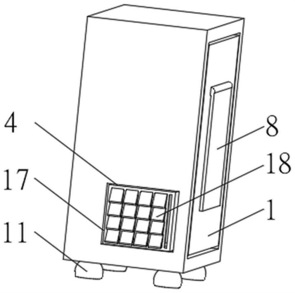
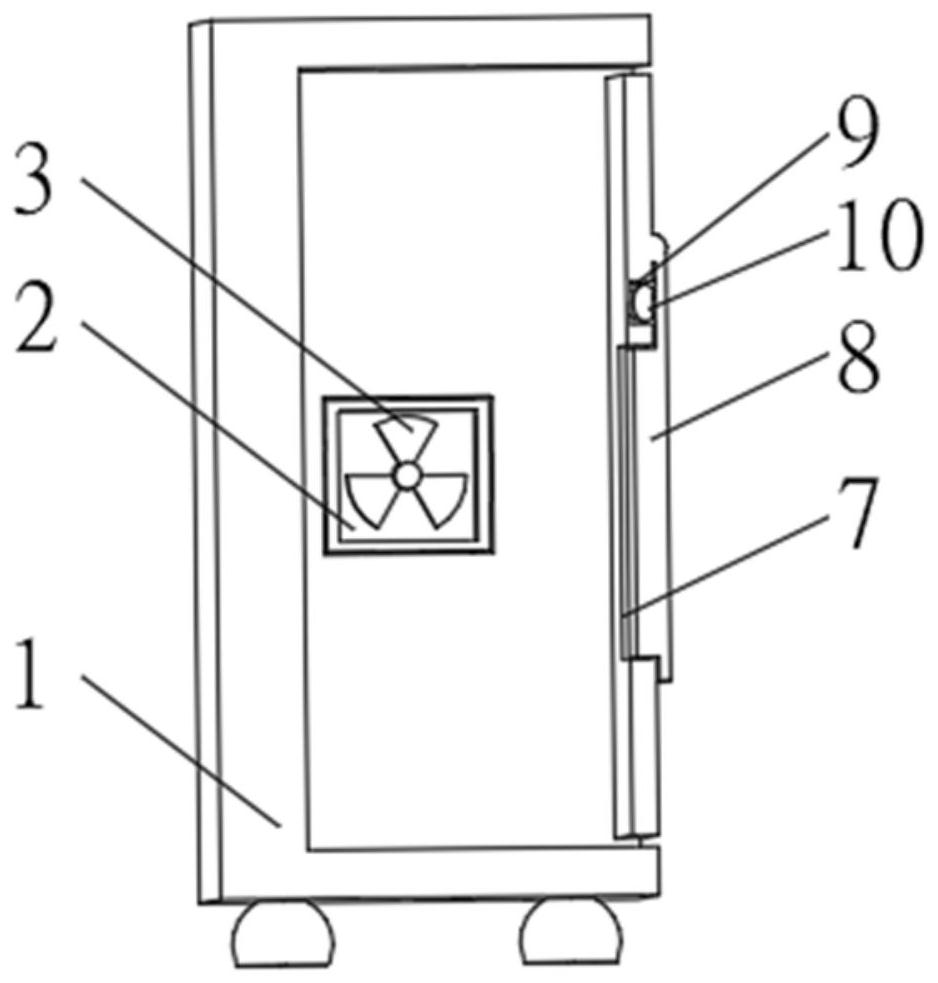
[0031] see Figure 1-3 , the present invention provides a technical solution: a temperature-controlled heat dissipation chassis, including an outer box 1, a base 11 is symmetrically installed on the bottom of the outer box 1, and an air exhaust port 2 is opened on one side of the outer box 1, and the air outlet 2 An exhaust fan 3 is installed inside, an air inlet 4 is provided on the side of the outer box 1 away from the air outlet 2, and a purification column 5 is evenly installed between the two sides of the inner wall of the air inlet 4, and a purification device 6 is evenly installed on the outside of the purification column 5 .

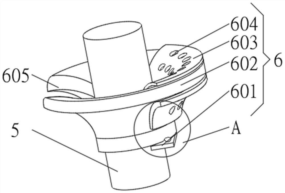
[0032] The purification device 6 includes a support plate 601 uniformly installed on one side of the purification column 5 , a purification cap 602 is installed on the top of the support plate 601 , and an adhesive layer 603 is symmetrically installed on one end of the purification cap 602 .

[0033] Limiting plates 17 are evenly installed betwe...

Embodiment 2

[0037] see Figure 1-4 , the present invention provides a technical solution: on the basis of Embodiment 1, an extension hole 604 is uniformly opened on the top of the purification cap 602, the extension hole 604 penetrates the adhesive layer 603, and the end of the purification cap 602 away from the adhesive layer 603 is provided with a The drop opening 605 matched with the purification column 5 , the purification column 5 is slidably connected with the inner wall of the drop opening 605 .

[0038] Balls 12 are uniformly installed on the top of the support plate 601 , and a recessed groove 13 matching the balls 12 is provided at the bottom of the purification cap 602 , and the balls 12 are slidably connected with the inner wall of the recessed groove 13 .

[0039] When in use, the air inside the outer box 1 is drawn to the outside by the exhaust fan 3 from the air outlet 2, and the inside of the outer box 1 sucks the outside air from the air inlet 4 to the inside of the outer...

Embodiment 3

[0041] see Figure 1-5 , the present invention provides a technical solution: on the basis of Embodiment 1, a temperature control opening 7 is opened on one side of the outer box 1, and a temperature control cover plate 8 is rotatably connected to the outside of the outer box 1 above the temperature control opening 7 , the temperature control cover plate 8 extends to the inside of the temperature control opening 7, a temperature control tank 9 is provided on one side of the outer box 1 close to the temperature control cover plate 8, and a temperature control device 10 is installed inside the temperature control tank 9. The control device 10 is connected with the temperature control cover plate 8.

[0042] The temperature control device 10 includes a rubber tube 101, the rubber tube 101 is evenly installed between the two sides of the inner wall of the temperature control tank 9, and a push ball 102 is evenly installed between the two sides of the inner wall of the temperature ...


PUM


Abstract

The invention discloses a temperature control heat dissipation case, and relates to the technical field of computer hardware equipment.The temperature control heat dissipation case comprises an outer case, bases are symmetrically installed at the bottom of the outer case, an air outlet is formed in one side of the outer case, an exhaust fan is installed in the air outlet, and an air inlet is formed in the side, away from the air outlet, of the outer case; purification columns are evenly installed between the two sides of the inner wall of the air inlet, and purification devices are evenly installed outside the purification columns. According to the temperature control heat dissipation case, dust in air can be prevented from entering the case to be accumulated when the air enters the case for heat dissipation, the possibility that the dust enters the case is reduced, excessive dust can automatically fall off when adhering to the surface of the filter part, the automation degree of the case is improved, and the heat dissipation efficiency is improved. Opening and closing of the heat dissipation openings can be automatically controlled according to the change of the external air temperature, the heat dissipation area is automatically controlled according to the external air temperature, and the intelligent degree of the device is improved.

Description

technical field [0001] The invention relates to the technical field of computer hardware equipment, in particular to a temperature-controlled cooling case. Background technique [0002] The computer is one of the greatest scientific and technological inventions in the 20th century. In various fields of industry, agriculture, and human society, the application of computers has made many major breakthroughs. Even the weather forecasts we listen to and watch every day are inseparable from computers. Scientific Computing. With the advancement of science and technology, the rapid development of various computer technologies and network technologies, the development of computers has entered a fast and new era. Computers have developed from single functions and large volumes to complex functions, small volumes, and resource networks. The chassis is an important part of the computer. Due to the long-term work of the chassis, the internal electrical components will generate a lot of...

Claims


Application Information

Patent Timeline
Patent Type & Authority Applications(China)
IPC IPC(8): G06F1/18G06F1/20
CPCG06F1/183G06F1/20
Inventor 李顺珍
Owner 绍兴市寅川软件开发有限公司
Why Eureka
Try Eureka