Coaxial circuit breaker tripping device

A technology of tripping device and circuit breaker, which is applied in the direction of protection switch operation/release mechanism, etc., which can solve the problems of complex structure of circuit breaker, easy burning of electromagnetic coil, difficulty in adapting electromagnetic tripping force, etc.

Pending Publication Date: 2021-05-18
TIANJIN JIAMEITE ELECTRIC EQUIP CO LTD
View PDF0 Cites 1 Cited by
  • Summary
  • Abstract
  • Description
  • Claims
  • Application Information

AI Technical Summary

Problems solved by technology

However, in normal operation, tripping the switch by mistake will cause unnecessary economic losses. Therefore, it is of great significance to improve the sensitivity and accuracy of the tripping mechanism of the circuit breaker
The traditional trip control uses a simple strong electromagnetic force to trigger the trip, and the electromagnetic coil is easily burned
In addition, conventional live wire circuit breakers, no matter single-phase or three-phase, the tripping devices are installed inside the respective circuit breakers, and the internal structure of the circuit breakers is complex
[0003] With the development of science and technology, the new national standard has been strict to 245-50 volts for the electronic circuit working voltage range of leakage protection circuit breakers. In the future, there will be a trend to match the international 30 volts. become more and more difficult to adapt

Method used


Image

  • Coaxial circuit breaker tripping device
  • Coaxial circuit breaker tripping device
  • Coaxial circuit breaker tripping device

Examples


Embodiment 1

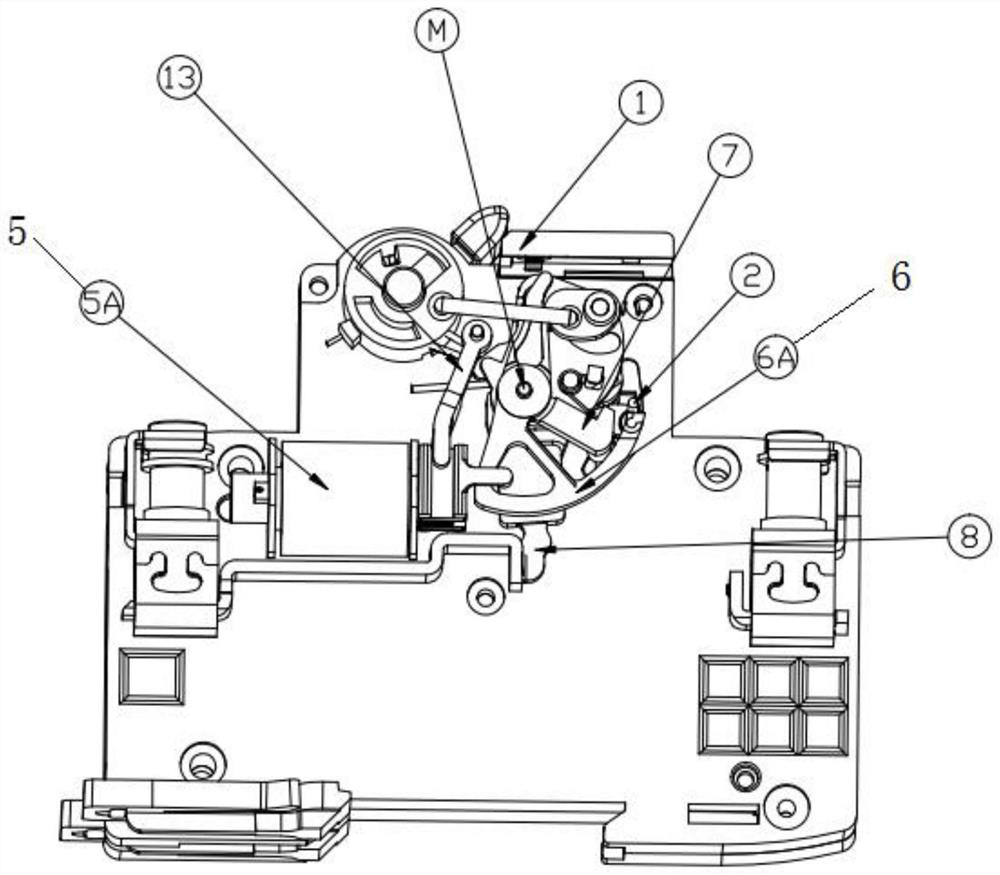
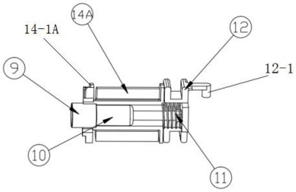
[0039] Such as figure 1 and figure 2 As shown, the electromagnetic tripping device 5 is a cold electromagnetic tripping device 5A, and the cold electromagnetic tripping device 5A includes a cold tripping permanent magnet static iron core 9, a cold tripping moving iron core 10, a tripping impact energy storage Spring 11, cold tripping striker 12 and cold electromagnetic coil 14A;

[0040] The cold electromagnetic coil 14A is wound on the cold electromagnetic coil frame 14-1A, the cold tripping moving iron core 10 is movably arranged in the shaft hole of the cold electromagnetic coil frame 14-1A, and the cold tripping permanent magnet static iron The core 9 is fixedly embedded in one end of the cold electromagnetic coil frame 14-1A, and the cold trip striker 12 is arranged at the other end of the cold electromagnetic coil frame 14-1A, and is connected with the cold trip moving iron core. 10 is fixedly connected, the tripping impact energy storage spring 11 is connected betwee...

Embodiment 2

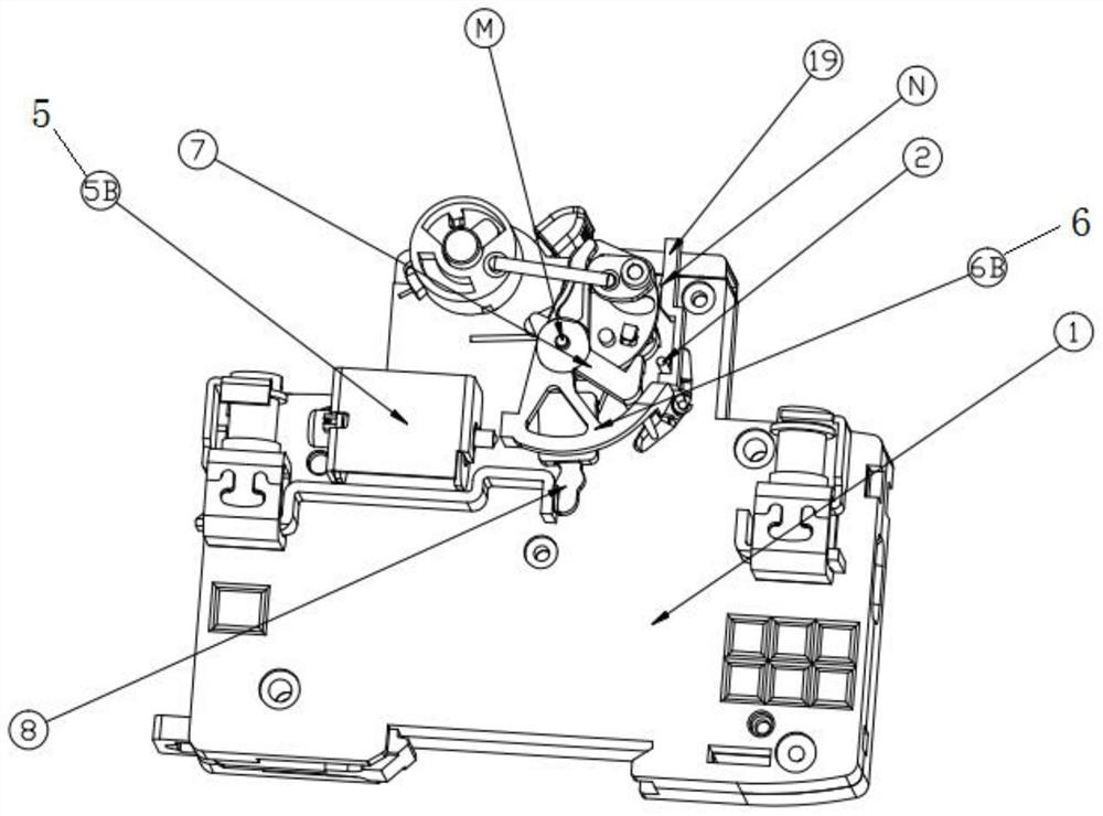
[0047] Such as image 3 and Figure 4 As shown, the electromagnetic tripping device 5 is a thermal electromagnetic tripping device 5B, and the thermal electromagnetic tripping device 5B includes a thermal electromagnetic coil 14B, a thermal tripping electromagnetic static iron core 15, a thermal tripping moving iron core 16, a thermal Tripping striker 17 and return spring 18; the thermal electromagnetic coil 14B is wound on the thermal electromagnetic coil frame 14-1B, and the thermal trip electromagnetic static iron core 15 is fixedly embedded in the thermal electromagnetic coil frame 14-1B At one end, the thermal tripping moving iron core 16 is movably arranged in the shaft hole of the thermal electromagnetic coil skeleton 14-1B, the thermal tripping moving iron core 16 and the thermal tripping striker 17 are co-cast together, the The thermal tripping striker 17 passes through the thermal tripping electromagnetic static iron core 15 and is close to the tripping pendulum 6; ...


PUM


Abstract

The invention discloses a coaxial circuit breaker tripping device which is characterized in that a tripping trigger device is arranged in a zero line circuit breaker and comprises an electromagnetic tripping device and a tripping pendulum bob, and the tripping pendulum bob and a zero line circuit breaker tripping lever are both arranged on a moving and static contact opening and closing mechanism of the zero line circuit breaker and share a common central shaft; the electromagnetic tripping device is arranged close to one end of the tripping pendulum bob and is used for impacting the tripping pendulum bob to swing; an interelectrode tripping linkage rod extends out of the shell of a live wire circuit breaker, is inserted into the zero line circuit breaker and is in contact with the other end of the tripping pendulum bob; and the zero line circuit breaker tripping lever extends out of the shell of the zero line circuit breaker and is inserted into a tripping tripping track of a live line circuit breaker mechanical linkage piece. According to the invention, the tripping trigger device is arranged on the contact opening and closing mechanism of the zero line circuit breaker to form a cross tripping structure of first live line and second zero line, so that the structure is simplified, the structure compactness is improved, and the reliability and the sensitivity of tripping and tripping actions are ensured.

Description

technical field [0001] The invention relates to the technical field of electrical switches, in particular to a tripping device for a coaxial circuit breaker. Background technique [0002] A circuit breaker is an electrical protection component that can quickly cut off the power supply when an abnormality occurs. However, in normal operation, accidentally tripping the switch will cause unnecessary economic losses. Therefore, it is of great significance to improve the sensitivity and accuracy of the tripping mechanism of the circuit breaker. The traditional trip control uses a simple strong electromagnetic force to trigger the trip, and the electromagnetic coil is easily burned. In addition, for conventional live wire circuit breakers, regardless of single-phase or three-phase, the tripping devices are all installed inside the respective circuit breakers, and the internal structure of the circuit breakers is complicated. [0003] With the development of science and technolog...

Claims


Application Information

Patent Timeline
Patent Type & Authority Applications(China)
IPC IPC(8): H01H71/10H01H71/24
CPCH01H71/10H01H71/24
Inventor 王克诚赵伟邹春胜
Owner TIANJIN JIAMEITE ELECTRIC EQUIP CO LTD
Why Eureka
Try Eureka