Circuit breaker

A circuit breaker, ratchet gear technology, applied in the field of circuit breakers, can solve problems such as applied, large loads

Pending Publication Date: 2021-05-18
MITSUBISHI ELECTRIC CORP
View PDF1 Cites 0 Cited by
  • Summary
  • Abstract
  • Description
  • Claims
  • Application Information

AI Technical Summary

Problems solved by technology

[0005] However, in a circuit breaker with a ratchet-type charging mechanism, when switching from the no-load period to the load period, a large load is suddenly applied to the transmission mechanism provided between the conveying pawl and the motor.

Method used


Image

  • Circuit breaker
  • Circuit breaker
  • Circuit breaker

Examples


Embodiment approach 1

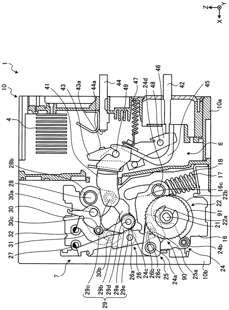
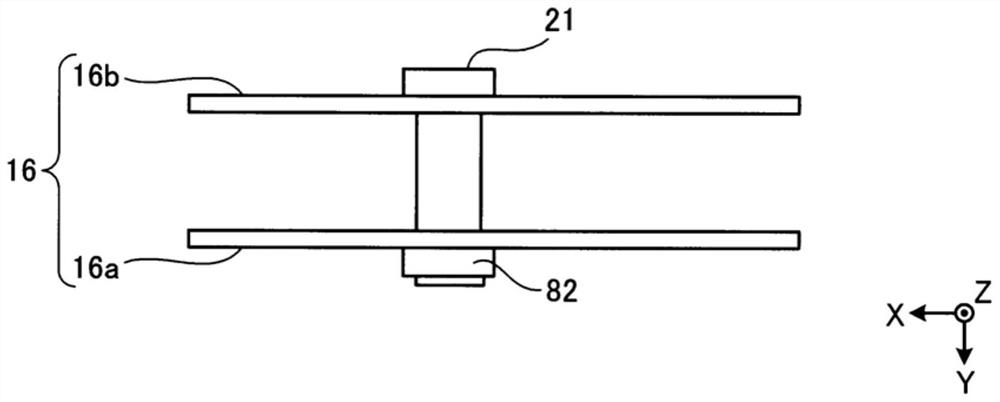
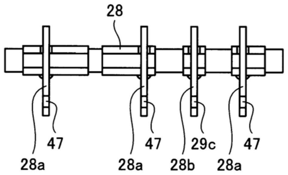
[0029] figure 1 It is a side cross-sectional view of the circuit breaker in an open state after charging according to Embodiment 1 of the present invention. figure 2 yes means figure 1 A state-of-state diagram of a part of the circuit breaker structure shown in the state. image 3 It is a diagram showing the relationship among the main shaft, the arm for the insulating link, and the insulating link according to the first embodiment. Figure 4 yes means figure 1 A state-of-state diagram of a part of the circuit breaker structure shown in the state. Figure 5 It is a sectional view of the circuit breaker main body when the circuit breaker according to Embodiment 1 is in a tripped state. Figure 6 yes means Figure 5 A state-of-state diagram of a part of the circuit breaker structure shown in the state.

[0030] figure 1 The shown circuit breaker 1 is an air circuit breaker, and is connected between a not-shown power supply device and a not-shown load device. The load de...


PUM


Abstract

A circuit breaker is provided with a ratchet gear, a conveying claw (92), an anti-reverse claw, a motor (94) and a load reduction part (100). The ratchet gear is pre-tightened in the first direction by the closing spring. An output shaft (94a) is attached to a transmission mechanism (95) provided between the motor (94) and the conveying claw (92), the output shaft (94a) is rotated to move the conveying claw (92) via the transmission mechanism (95), and the ratchet gear is rotated in a second direction opposite to the first direction. The load reduction part (100) reduces the rotational speed of the motor (94) during a period from when the rotation of the ratchet gear rotated in the second direction by the conveying claw (92) in the first direction is restricted by the anti-reverse claw until the next rotation of the ratchet gear in the second direction by the conveying claw (92).

Description

technical field [0001] The invention relates to a circuit breaker which stores energy in a closing spring by a motor, and sets a circuit in a closed state by the force of the stored closing spring. Background technique [0002] Conventionally, there is known a circuit breaker provided with a ratchet charging mechanism for charging a closing spring by an electric motor. For example, Patent Document 1 discloses a circuit breaker that has: a ratchet gear that is biased by a closing spring; a conveyance claw that engages with the ratchet gear; and a motor that rotates the ratchet gear through the conveyance claw. And make the closing spring store energy. [0003] In circuit breakers with a ratchet charging mechanism, periods of load and periods of no load occur alternately. The on-load period is a period from when the feed pawl starts to rotate the ratchet gear in the direction opposite to the biasing direction of the closing spring until the rotation of the ratchet gear in th...

Claims


Application Information

Patent Timeline
Patent Type & Authority Applications(China)
IPC IPC(8): H01H71/70
CPCH01H71/70
Inventor 假重太智
Owner MITSUBISHI ELECTRIC CORP
Why Eureka
Try Eureka