

Socket and using method thereof
A technology of sockets and inserts, which is applied in the direction of contact parts, fixed/insulated contact components, electrical components, etc., and can solve the problems of laborious insertion, loose insertion, and poor contact of inserts
- Summary
- Abstract
- Description
- Claims
- Application Information
AI Technical Summary
Problems solved by technology
Method used
Image

Examples
Embodiment 1
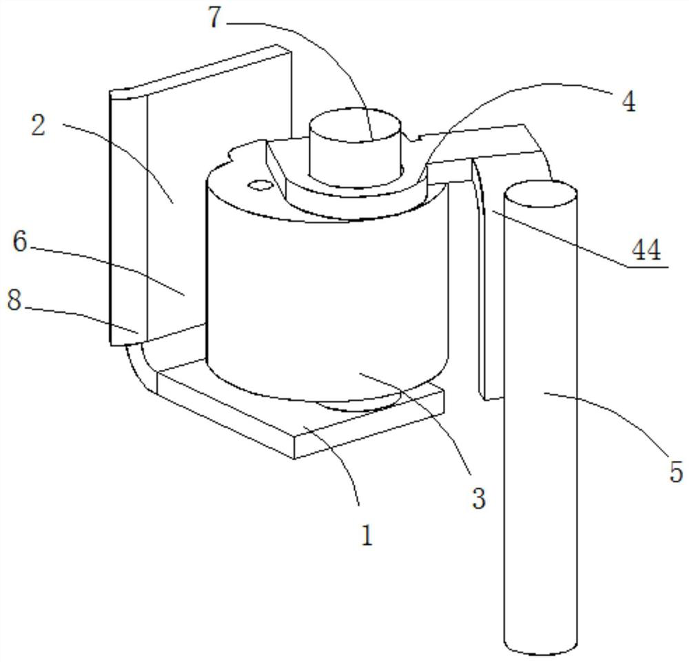
[0033] For a socket provided by Embodiment 1 of the present invention, please refer to figure 1 , figure 2 , image 3 , Figure 4 and Figure 5 As shown, it includes a housing, a socket provided on the housing, and a contact mechanism provided in the housing. The socket and the contact mechanism are arranged in cooperation. The contact mechanism includes: a base 1; a rotating shaft 7, and the rotating shaft 7 is vertically arranged on the On the base 1; the base plate 2, the base plate 2 is vertically arranged at the end of the base 1, and has an L-shaped structure with the base 1; The end with a large eccentricity is set close to the socket, and there is a gap 6 between the eccentric wheel 3 and the base plate 2; the switch paddle 4, the switch paddle 4 is set on the eccentric wheel 3; and the terminal 5, the terminal 5 is set on the housing Above, the connecting post 5 is arranged in cooperation with the switch paddle 4 , wherein the size of the gap 6 can be changed by ...
Embodiment 2
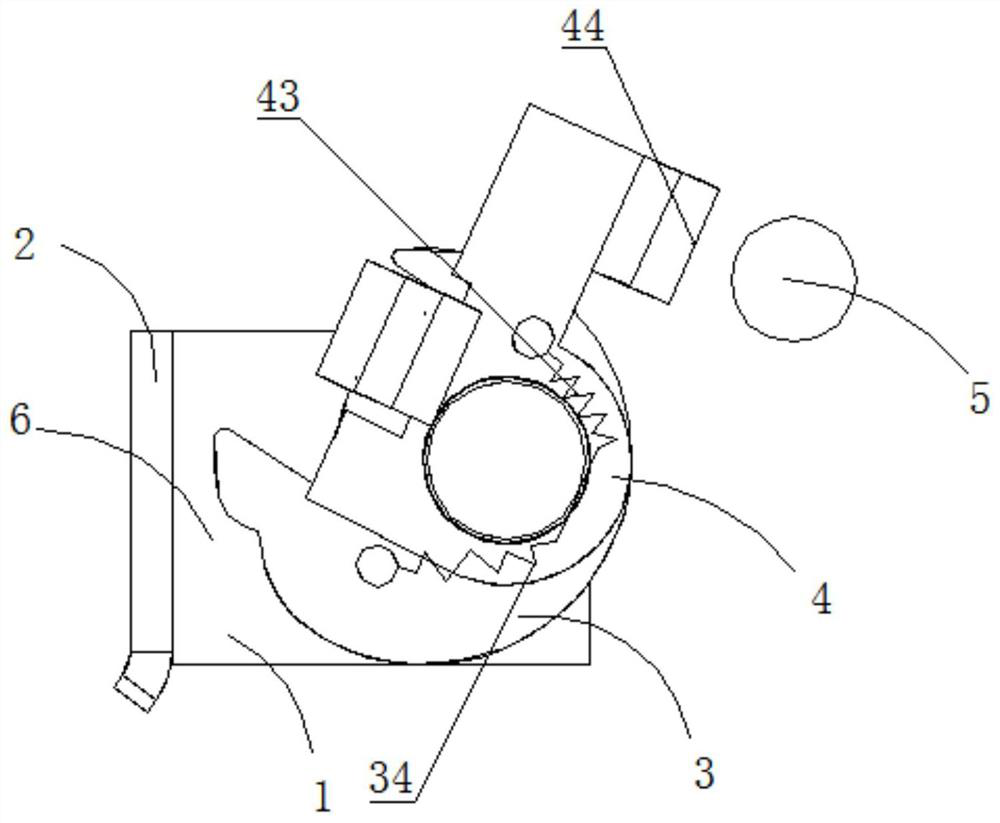
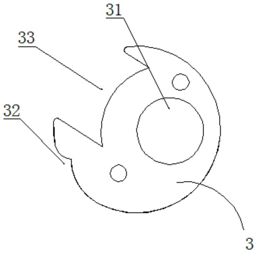
[0036] For a socket provided by Embodiment 2 of the present invention, please refer to figure 1 , figure 2 , image 3 , Figure 4 and Figure 5 As shown, it includes a housing, a socket provided on the housing, and a contact mechanism provided in the housing. The socket is arranged in cooperation with the contact mechanism. The contact mechanism includes: a base 1; a rotating shaft 7, which is vertically arranged on the base 1; the base plate 2, the base plate 2 is set at the end of the base 1; the eccentric wheel 3, the eccentric wheel 3 is provided with an eccentric hole 31 that matches the rotation of the rotating shaft 7, and the end of the eccentric wheel 3 with a large eccentricity is set close to the socket, and the eccentric wheel 3 There is a gap 6 between the base plate 2; the switch paddle 4, the switch paddle 4 is arranged on the eccentric wheel 3; , wherein the rotation of the eccentric wheel 3 can change the size of the gap 6, and the switch paddle 4 can be ...
Embodiment 3
[0039] A socket provided by Embodiment 3 of the present invention is basically the same as Embodiment 2, the difference being that the eccentric wheel 3 is provided with a first return spring 34; one end of the first return spring 34 is connected to the eccentric wheel 3, and the other end is connected to the rotating shaft 7 Connection (it can be connected with the shell, the base, and the substrate, and it can be connected according to the situation). The side of the eccentric wheel 3 away from the socket is provided with a limiting groove 33, the switch paddle 4 is provided with a shaft hole 41 matching the rotating shaft 7, the switch paddle 4 is provided with a driving piece 42, and the driving piece 42 can be positioned in the limiting groove 33. Move in the inner circumferential direction; the switch paddle 4 is provided with a second return spring 43, one end of the second return spring 43 is connected with the switch paddle 4, and the other end is connected with the ro...
PUM
 Abstract
Description
Claims
Application Information