Anti-seismic cable bridge

A cable tray, anti-vibration technology, applied in electrical components, springs/shock absorbers, vibration suppression adjustment, etc., can solve the problems of cable tray shaking, loose connection and easy falling off, heavy cable weight, etc., to achieve good seismic resistance, reduce Impact, simple structure effect

Active Publication Date: 2021-05-18
广东桥鑫实业有限公司
View PDF11 Cites 8 Cited by
  • Summary
  • Abstract
  • Description
  • Claims
  • Application Information

AI Technical Summary

Problems solved by technology

[0003] Existing cable bridges are usually installed on the ceiling of the building. When the cable bridge is heavy due to the weight of the cables on the entire cable bridge, it is easy to cause the entire cable bridge to shake and cause a gap between the entire bridge and the wall. The connection is loose and easy to fall off. A kind of anti-seismic cable tray is proposed to solve the above problems

Method used


Image

  • Anti-seismic cable bridge
  • Anti-seismic cable bridge
  • Anti-seismic cable bridge

Examples


Embodiment 1

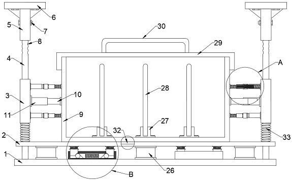
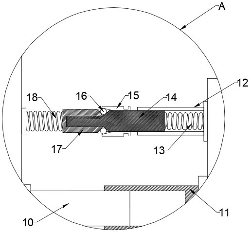
[0025] see Figure 1~5 , in an embodiment of the present invention, an anti-seismic cable tray includes a cable placement frame 9, a bottom fixing plate 1 and two upper fixing seats 6, the bottom fixing plate 1 is provided with a buffer adjustment plate 2, the A bottom anti-seismic mechanism is arranged between the buffer adjustment plate 2 and the bottom end fixed plate 1, and the cable placement frame 9 is slidably installed on the upper end surface of the buffer adjustment plate 2, and the two upper end fixing seats 6 and the bottom end fixed plate 1 are provided with a fixed shaft body 4, and a multi-stage anti-seismic mechanism is arranged between the fixed shaft body 4 and the side wall of the cable placement frame 9, and the multi-stage anti-seismic mechanism includes two rod sleeves 3, and two The rod sleeves 3 are respectively slidably mounted on the outer sidewalls of the two fixed shaft bodies 4, and the two rod sleeves 3 are provided with two shock absorbing sleeve...

Embodiment 2

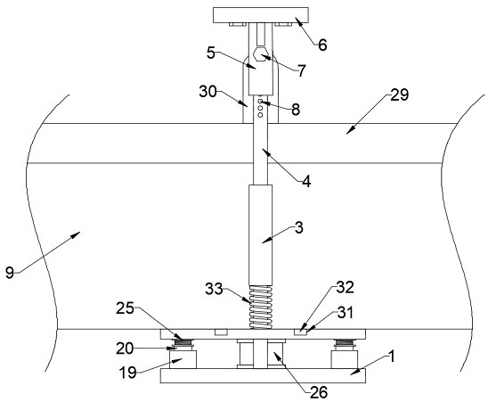
[0032] see figure 1 The difference between the embodiment of the present invention and embodiment 1 is that the two upper fixing seats 6 are provided with adjusting sleeves 5 fixedly connected thereto, and the two fixed shafts 4 are provided with multiple An adjustment through hole 8, one end of the fixed shaft body 4 is set in the inner cavity of the adjustment sleeve 5 and the side wall of the fixed shaft body 4 is slidingly connected with the inner side wall of the adjustment sleeve 5, and the adjustment sleeve 5 is provided with There is an adjusting bolt 7 for fixing the end of the fixed shaft 4. When installing the entire bridge, the end of the fixed shaft 4 can first slide on the inner wall of the adjusting sleeve 5 to adjust the height of the entire bridge. , and then the fixed shaft body 4 is fixed on the adjusting sleeve 5 through the cooperation of the adjusting bolt 7 and the adjusting through hole 8 .

[0033] The working principle of the invention is as follows:...


PUM


Abstract

The invention provides an anti-seismic cable bridge which comprises a cable placing frame, a bottom end fixing plate and two upper end fixing seats. A buffer adjusting plate is arranged on the bottom end fixing plate, a bottom end anti-seismic mechanism is arranged between the buffer adjusting plate and the bottom end fixing plate, and the cable placing frame is slidably installed on the upper end face of the buffer adjusting plate. Fixing shaft bodies are arranged between the two upper end fixing seats and the bottom end fixing plate, a multi-stage anti-seismic mechanism is arranged between the fixing shaft bodies and the side wall of the cable placement frame, the multi-stage anti-seismic mechanism comprises two rod sleeves, and the two rod sleeves are slidably installed on the outer side walls of the two fixing shaft bodies correspondingly; the side walls of the two rod sleeves are both provided with two damping sleeves fixedly connected with the rod sleeves, the inner side walls of the two damping sleeves are both provided with buffer shaft bodies slidably connected with the inner side walls of the damping sleeves, the cable bridge is simple in structure, the adverse effect on the whole cable bridge when vibration is generated can be effectively reduced, and therefore the safety of the whole bridge is improved.

Description

technical field [0001] The invention relates to the technical field of cable bridges, in particular to an anti-seismic cable bridge. Background technique [0002] Cable trays are divided into trough type, tray type, ladder type, grid type and other structures, and are composed of brackets, supporting arms and installation accessories. The bridge frame in the building can be erected independently or laid on various buildings (structures) and pipe gallery supports. It should reflect the characteristics of simple structure, beautiful appearance, flexible configuration and convenient maintenance. All parts need to be galvanized . [0003] Existing cable bridges are usually installed on the ceiling of the building. When the cable bridge is heavy due to the weight of the cables on the entire cable bridge, it is easy to cause the entire cable bridge to shake and cause a gap between the entire bridge and the wall. The connection is loose and easy to fall off. A kind of anti-seismi...

Claims


Application Information

Patent Timeline
Patent Type & Authority Applications(China)
IPC IPC(8): H02G3/04H02G3/30F16F15/067
CPCF16F15/067H02G3/0406H02G3/0456H02G3/30
Inventor 殷华伟
Owner 广东桥鑫实业有限公司
Why Eureka
Try Eureka