Highly automated fly ash curing device

A technology of fly ash solidification and solidification box, which is applied in the direction of unloading device, cement mixing device, clay preparation device, etc. It can solve the problems of air pollution, surface roughness, biological and human hazards, etc., and achieve the effect of ensuring stability

Inactive Publication Date: 2020-10-09
江苏西玛环境科技有限公司
View PDF0 Cites 1 Cited by
  • Summary
  • Abstract
  • Description
  • Claims
  • Application Information

AI Technical Summary

Problems solved by technology

[0002] Tiny ash particles discharged from the combustion process of fuel (mainly coal), whose particle size is generally between 1 and 100 μm, also known as fly ash or soot, fine solid particles in the flue gas ash produced by fuel combustion, such as Coal-fired power plants collect fine ash from flue gas. Fly ash is formed when coal powder enters the furnace at 1300-1500 ° C and undergoes heat absorption by the hot surface under suspension combustion conditions and then cools down. Due to the effect of surface tension, fly ash Most of them are spherical, with smooth surface and small micropores. Some of them are cohesive due to collision with each other in the molten state, and become honeycomb composite particles with rough surface and many corners. , boiler type, combustion conditions and collection methods, etc. The emission of fly ash is directly related to the ash content in coal combustion. According to the coal consumption in China, 250-300kg of fly ash is produced by burning 1 ton of coal. A large amount of fly ash such as If it is not controlled or treated, it will cause air pollution, and if it enters the water, it will block the river course. Some of the chemical substances will cause harm to organisms and humans. In order to eliminate the impact of fly ash, we often use a fly ash curing device to solidify the fly ash. Then it will be landfilled, and the existing fly ash solidification device cannot automatically realize the solidification of fly ash, and needs to be manually controlled for each step. Therefore, in order to solve the above problems, we have designed a highly automated fly ash solidification device

Method used


Image

  • Highly automated fly ash curing device
  • Highly automated fly ash curing device
  • Highly automated fly ash curing device

Examples


Embodiment Construction

[0030] The following will clearly and completely describe the technical solutions in the embodiments of the present invention with reference to the accompanying drawings in the embodiments of the present invention. Obviously, the described embodiments are only some, not all, embodiments of the present invention. Based on the embodiments of the present invention, all other embodiments obtained by persons of ordinary skill in the art without making creative efforts belong to the protection scope of the present invention.

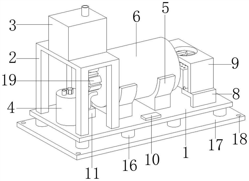
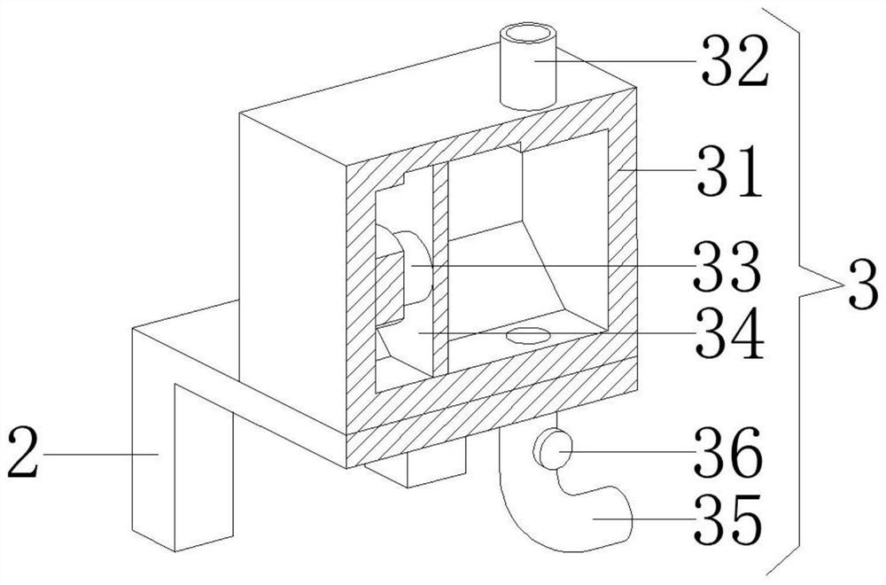
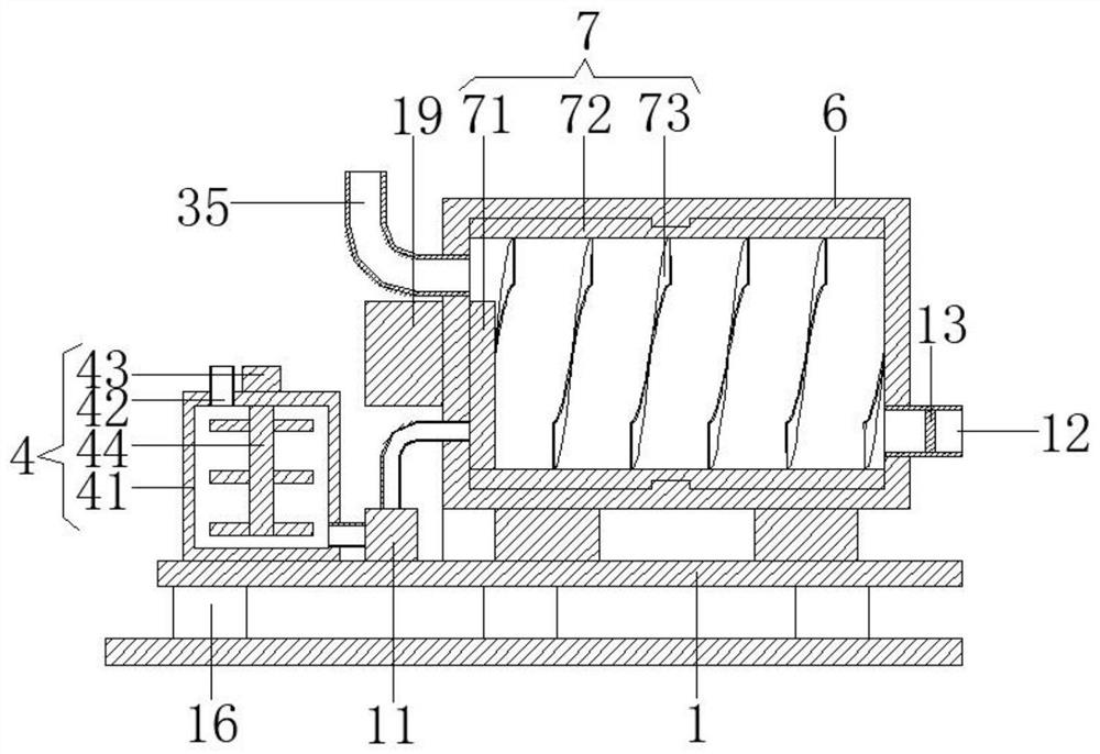
[0031] see Figure 1-5 , the present invention provides a technical solution: a highly automated fly ash solidification device, including a bottom plate 1, a quantitative feeding structure 3, a chelating agent stirring structure 4, a chelating structure 7, a curing structure 9 and a discharge structure 14;

[0032] Bottom plate 1: a support platform 2 is provided on the left side of the upper surface, and brackets 5 are arranged symmetrically in the middle of th...


PUM


Abstract

The invention discloses a highly automated fly ash curing device. The highly automated fly ash curing device comprises a bottom plate, a quantitative discharging structure, a chelating agent mixing structure, a chelating structure, a curing structure and an unloading structure. A supporting table is arranged on the left side of the upper surface of the bottom plate, brackets are symmetrically arranged left and right in the middle of the upper surface of the bottom plate, the inner arc-shaped walls of the brackets are fixedly connected to an outer arc-shaped surface of a chelating barrel, L-shaped plates are symmetrically arranged front and back on the right side of the upper surface of the bottom plate, a metering water pump is arranged on the left side of the upper surface of the bottom plate, a water outlet in the right side surface of the metering water pump communicates to a water inlet in the lower end of the left side surface of the chelating barrel through a pipeline, and a conveying pipe is arranged at a discharge position at the lower end of the right side surface of the chelating barrel. The highly automated fly ash curing device can control the discharging amount of materials and further can overturn and chelate the internal materials, so that fly ash is cured to cement and the materials can be air-dried and cured quickly. Influence caused by vibration when equipmentoperates can be further reduced, and the stability of an integral structure is protected.

Description

technical field [0001] The invention relates to the technical field of fly ash processing equipment, in particular to a highly automated fly ash solidification device. Background technique [0002] Tiny ash particles discharged from the combustion process of fuel (mainly coal), whose particle size is generally between 1 and 100 μm, also known as fly ash or soot, fine solid particles in the flue gas ash produced by fuel combustion, such as Coal-fired power plants collect fine ash from flue gas. Fly ash is formed when coal powder enters the furnace at 1300-1500 °C and undergoes heat absorption by the hot surface under suspension combustion conditions and then cools down. Due to the effect of surface tension, fly ash Most of them are spherical, with smooth surface and small micropores. Some of them are cohesive due to collision with each other in the molten state, and become honeycomb composite particles with rough surface and many corners. , boiler type, combustion conditions...

Claims


Application Information

Patent Timeline
IPC IPC(8): B28C7/06B28C7/04B28C5/20B28C7/16B28C7/12B28C7/00B09B3/00F16F15/04
CPCB09B3/00B28C5/20B28C5/2054B28C7/0007B28C7/0418B28C7/067B28C7/126B28C7/167F16F15/04
Inventor 徐全云高东生
Owner 江苏西玛环境科技有限公司
Why Eureka
Try Eureka