Unlock instant, AI-driven research and patent intelligence for your innovation.
A high-reflectivity powder surface spraying device for lighting processing
What is Al technical title?
Al technical title is built by PatSnap Al team. It summarizes the technical point description of the patent document.
A high-reflectivity, surface spraying technology, applied in the direction of the spraying device, can solve the problems of inconvenient loading and unloading, uneven powder spraying, etc., and achieve the effect of uniform powder
Active Publication Date: 2022-04-19
江门市天邦照明电器有限公司
View PDF6 Cites 0 Cited by
Summary
Abstract
Description
Claims
Application Information
AI Technical Summary
This helps you quickly interpret patents by identifying the three key elements:
Problems solved by technology
Method used
Benefits of technology
Problems solved by technology
[0005] In order to overcome the shortcomings of the prior art that the spraying powder is not uniform enough and the loading and unloading is inconvenient, the technical problem of the present invention is to provide a high-reflectance coating for lighting processing that can be automatically loaded and unloaded, and can be sprayed evenly. Powder surface spraying device
Method used
Image
Click on the blue label to locate the original text in one second.
Reading with bidirectional positioning of images and text.
Examples
Embodiment 1
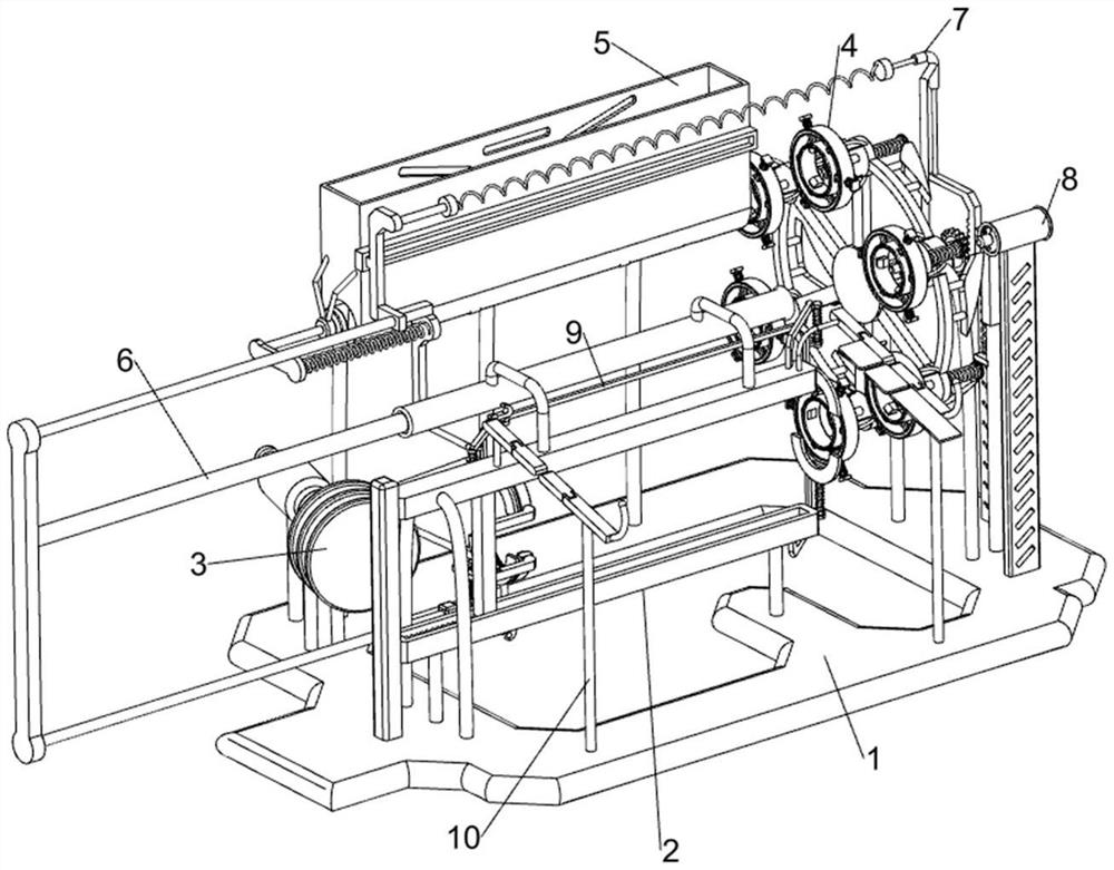
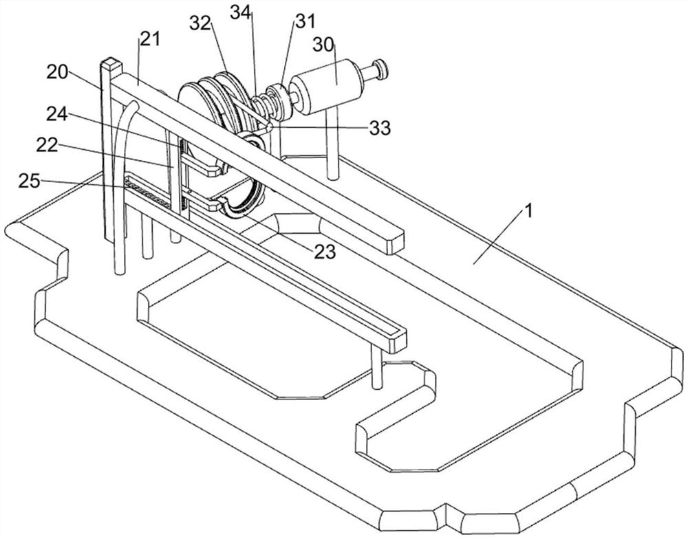
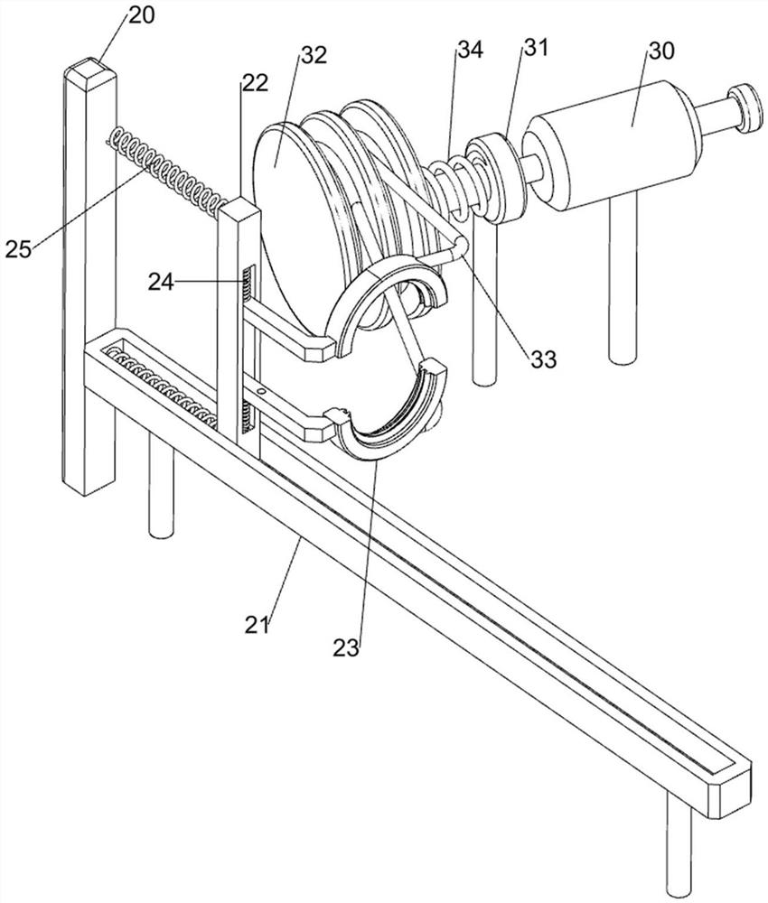
[0034] A high-reflectivity powder surface spraying device for lighting processing, such as figure 1 , figure 2 , image 3 , Figure 4 and Figure 5 As shown, it includes a base 1, a spraying mechanism 2, a feeding mechanism 3 and a feeding mechanism 4. The left side of the base 1 is provided with a spraying mechanism 2, the upper left side of the base 1 is provided with a feeding mechanism 3, and the upper left side of the base 1 is provided with a feeding mechanism 3. The side is provided with feeding mechanism 4.
[0035] The spraying mechanism 2 includes a mounting column 20, a slide rail 21, a chute plate 22, an annular nozzle 23, a first tension spring 24 and a return spring 25, the left side of the base 1 is fixedly connected with the mounting column 20, and the right side of the mounting column 20 The upper part and the upper front side of the base 1 are connected with slide rails 21, slide rails 21 are provided with a chute plate 22, and the chute plate 22 is symm...
Embodiment 2
[0040] On the basis of Example 1, such as Figure 6 , Figure 7 , Figure 8 , Figure 9 and Figure 10 As shown, a feeding assembly 5 is also included, and the feeding assembly 5 includes a fixed rod 50, a feeding frame 51, an elastic sheet 52, a sliding seat 53, a push plate 54 and a connecting plate 55, and the rear side of the base 1 is evenly spaced and fixed. Three fixed rods 50 are connected, and a feeding frame 51 is connected between the tops of the fixing rods 50. The bottom of the feeding frame 51 is symmetrically connected with an elastic piece 52, and the left side of the feeding frame 51 is connected with a sliding seat 53, and the sliding seat 53 is of a sliding type A push plate 54 is provided, and a connecting plate 55 is connected to the left end of the push plate 54 .
[0041] Also includes a power assembly 6, the power assembly 6 includes a guide rail 60, a sliding rod 61, a sliding sleeve 62, a sliding rail 63, a rack 64, a one-way gear 65, a first spri...
PUM
Abstract
The invention relates to a spraying device, in particular to a high-reflectivity powder surface spraying device for lighting processing. The technical problem of the present invention is to provide a high-reflectivity powder surface spraying device for lighting processing that can automatically load and unload materials and can spray uniformly. A high-reflectivity powder surface spraying device for lighting processing, comprising: a base, a spraying mechanism is arranged on one side of the base; a material delivery mechanism, the material delivery mechanism is arranged on one side of the base; The material delivery mechanism is arranged on the side of the base away from the material delivery mechanism. Through the cooperation of the feeding component and the transmission component, the present invention makes the lighting automatically fall on the material transfer mechanism and is fixed, and the sprayed lighting is pushed out through the pushing component. The whole process does not require people to perform too much operation, which is very convenient .
Description
technical field [0001] The invention relates to a spraying device, in particular to a high-reflectivity powder surface spraying device for lighting processing. Background technique [0002] In the past, the surface protection and decoration of the lighting industry usually used electroplating treatment, which has beautiful, diverse, decorative and anti-corrosion properties. However, this will result in low luminous flux of the lighting and requires a larger power lighting to achieve the required brightness. [0003] In order to respond to the energy saving and emission reduction advocated by the country, manufacturers often spray high reflectivity powder on the surface of the lighting to increase the reflection efficiency of the light. The existing spraying device, such as a Chinese patent with the patent announcement number CN211538278U, discloses a LED lamp Phosphor powder spraying device for production, including base, bottom column, vertical plate, horizontal plate, stor...
Claims
Application Information
Patent Timeline
Application Date:The date an application was filed.
Publication Date:The date a patent or application was officially published.
First Publication Date:The earliest publication date of a patent with the same application number.
Issue Date:Publication date of the patent grant document.
PCT Entry Date:The Entry date of PCT National Phase.
Estimated Expiry Date:The statutory expiry date of a patent right according to the Patent Law, and it is the longest term of protection that the patent right can achieve without the termination of the patent right due to other reasons(Term extension factor has been taken into account ).
Invalid Date:Actual expiry date is based on effective date or publication date of legal transaction data of invalid patent.
