Improved piston detection machine

A testing machine and an improved technology, applied in the field of testing machines, can solve the problems of delay in feeding and poor continuity, and achieve the effects of rapid replacement, shortening cycle period and improving detection accuracy

Pending Publication Date: 2021-05-25
一和科技(常熟)有限公司
View PDF0 Cites 0 Cited by
  • Summary
  • Abstract
  • Description
  • Claims
  • Application Information

AI Technical Summary

Problems solved by technology

[0002] In the actual use of existing piston detectors, trolleys are generally used to push stacked material frames at the loading station, and after a group of material frames are emptied, they can be moved by clamping jaws or The manipulator grabs the empty material frame and transfers it to the empty material frame trolley of the unloading station, and after the material frame is emptied from the trolley at the loading station, it will take time to replace the material frame of the trolley, which will cause a delay in loading , poor coherence, and how to realize the adjustment and replacement of various products and detection devices in the piston detection machine integrated with size detection, shape tolerance detection and height detection has attracted more and more attention

Method used


Image

  • Improved piston detection machine
  • Improved piston detection machine
  • Improved piston detection machine

Examples


Embodiment Construction

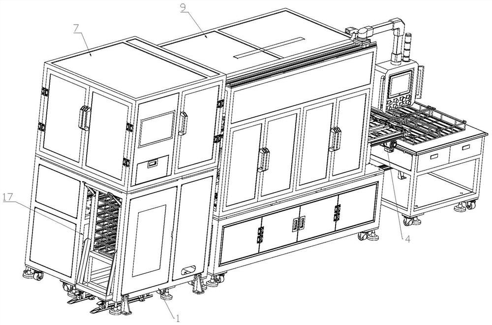
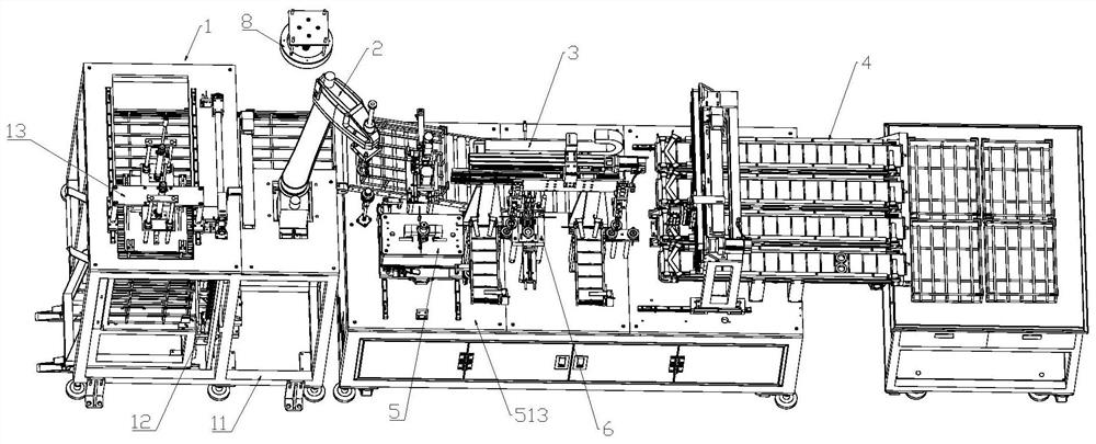
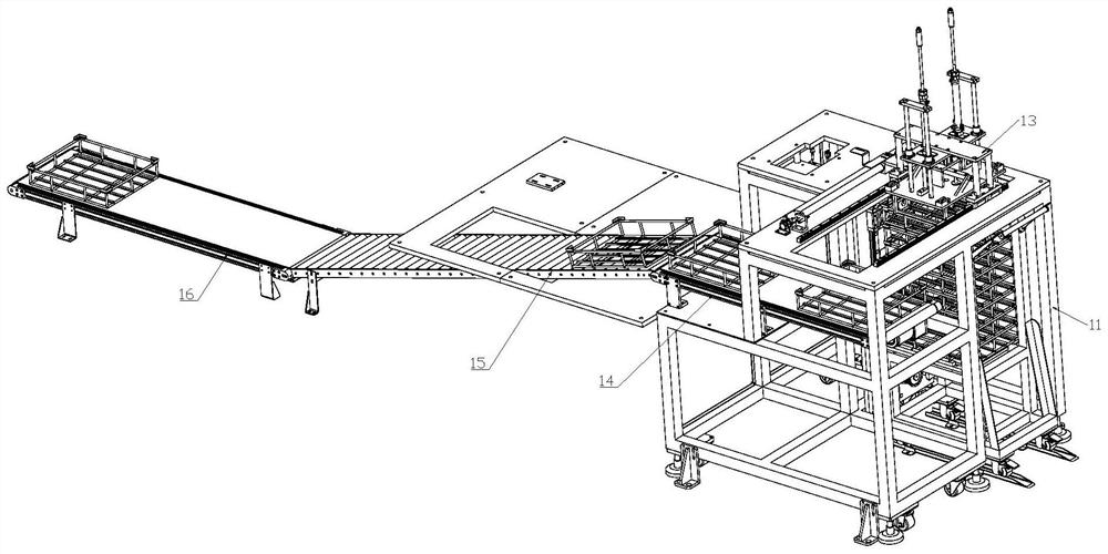
[0039]CombineFigure 1 to 16An improved piston detector, in the present embodiment, including upper level 1, detection position, upper robot 2, handling mechanism 3 and a registered position 4, and the upper robot 2 is located in the upper position 1 and Between the detection position, it is used to feed the product at the upper position 1 to the detection bit, and the detection bit is used to detect whether the product is qualified. If so, the product is sent to the receiving position 4, the receiving position 4 For collecting qualified products; the upper level 1 includes a lift rack 11, a lifting portion 12, a casing jam portion 13, a sheet conveyor belt 14, a non-warrant conveying line 15, and a frame conveyor belt 16; lifting unit 12 The upper channel bits 17 fixed to the lift rack 11 is supplied to the housing frame of the pallet sheet to the material frame claw portion 13; the casing jaw portion 13 slides on the lifting rack 11, which is capable of clamping The material is sen...


PUM


Abstract

The invention provides an improved piston detection machine. The improved piston detection machine comprises a feeding station, a detection station, a feeding manipulator, a carrying mechanism and a receiving station, wherein the feeding station comprises a lifting rack, a lifting part, a material frame clamping jaw part, a feeding conveying belt, an unpowered conveying line and a frame collecting conveying belt; the lifting part is fixed to the feeding channel position of the lifting rack and used for lifting and conveying stacked material frames to the position below the material frame clamping jaw part; the material frame clamping jaw part is connected to the lifting rack in a sliding mode and can clamp and convey the material frames to the feeding conveying belt, and the feeding conveying belt is fixed to the lifting rack and used for being matched with the feeding manipulator to clamp products for feeding; the unpowered conveying line is obliquely arranged, the high end of the unpowered conveying line is connected with the feeding conveying belt, and the bottom end of the unpowered conveying line is connected with the frame collecting conveying belt; and the frame collecting conveying belt is used for collecting the empty material frames. According to the improved piston detection machine, the material storage is increased, the time and the cycle period for replacing the material frames are shortened, and the universality is better.

Description

Technical field[0001]The present invention relates to a detecting machine, in particular a modified piston detector.Background technique[0002]Existing piston detection machine, during the actual use, since the trolley pushed the cartlette in the upper station, it can be passed through the jaw or Manipulating the air frame to the blank frame of the blank, and after the feed frame of the feed frame, it will take the time to replace the cartridge frame, which will cause the delay of the above. Poor coherence, and in the piston detection machine for integrated dimensional detection, shade tolerance detection, and highly detected, how many products and adjustment and replacement of detection devices are also increasingly attached.[0003]Therefore, an improved piston detector is improved in a periodless of increasing the storage, shortening the replacement frame, not only to increase the replacement frame, but also improved the piston detection machine.Inventive content[0004]It is an objec...

Claims


Application Information

Patent Timeline
Patent Type & Authority Applications(China)
IPC IPC(8): B07C5/04B07C5/02B07C5/36
CPCB07C5/02B07C5/04B07C5/362
Inventor 朱伟华
Owner 一和科技(常熟)有限公司
Why Eureka
Try Eureka