
Dismounting and tightening equipment for valve connecting bolt

A technology for connecting bolts and valves, which is applied in the field of dismantling and tightening equipment for connecting bolts of large or heavy valves, and can solve problems such as hidden dangers to the safety of operators, low production efficiency, and inability to adapt to bolting machines.

Active Publication Date: 2021-05-25
CHONGQING JIUHUAN MACHINERY & ELECTRIC CO LTD
View PDF8 Cites 4 Cited by
  • Summary
  • Abstract
  • Description
  • Claims
  • Application Information

AI Technical Summary

Problems solved by technology

However, relying on manual knocking, disassembly and tightening results in low production efficiency, long manual operation time for operators, high labor intensity, and safety risks at any time. There is also the problem of uneven force in the way of manual beating, which can easily cause uneven force on the connecting bolts of the valve, making the valve connection not tight or there are gaps
At the same time, the general bolt-tightening mechanism often has errors in the machining process due to the center distance of the bolt holes, and the specifications of different valves are inconsistent. The general bolt-tightening machine cannot adapt to valves of different specifications, resulting in low work efficiency.

Method used


Image

  • Dismounting and tightening equipment for valve connecting bolt
  • Dismounting and tightening equipment for valve connecting bolt
  • Dismounting and tightening equipment for valve connecting bolt

Examples


Embodiment Construction

[0031]Next, the technical solutions in the embodiments of the present invention will be apparent from the embodiment of the present invention, and it is clearly described, and it is understood that the described embodiments are merely embodiments of the present invention, not all of the embodiments. Based on the embodiments of the present invention, there are all other embodiments obtained without making creative labor without making creative labor premises. Moreover, the terms "first", "second", etc. are only used to describe purposes, and cannot be understood as an indication or implies relative importance or implicitly indicated the number of techniques indicated.

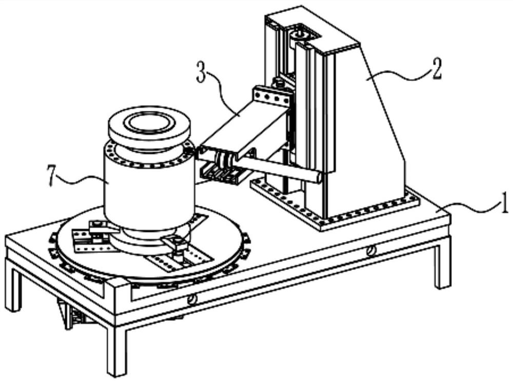
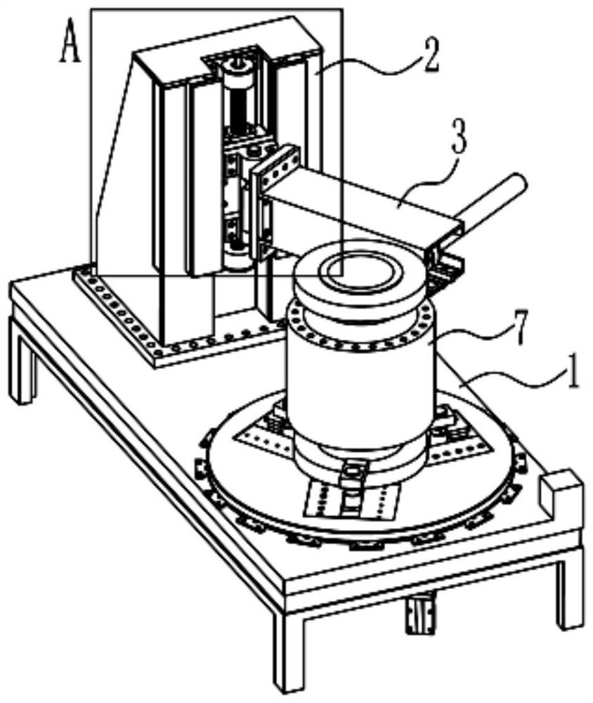
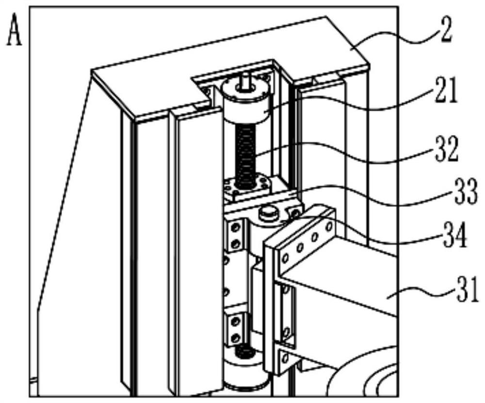
[0032]Such asFigures 1 to 10As shown, the present invention provides a valve connection bolt disassembly and tightening apparatus including a table 1, a column 2, a movable connection arm 3, a wrench connection device 4, a rotating device 5, and a compression device 6; Installing the column 2, the rotating device 5 is ro...


PUM


Abstract

The invention discloses dismounting and tightening equipment for a valve connecting bolt. The dismounting and tightening equipment comprises a workbench, a stand column, a movable connecting arm, a solid wrench connecting device, a rotating device, and a pressing device. The stand column and the rotating device are installed on the workbench. The movable connecting arm is connected with the stand column and the solid wrench connecting device. The pressing device is installed on the rotating device; a valve is arranged on the rotating device; and the rotating device enables the valve to rotate in the axial direction of the rotating device. The movable connecting arm comprises a shell, a lead screw, a sliding block, a hinge lug, and a first hydraulic cylinder. Two ends of the lead screw are rotationally connected with the stand column; the sliding block is in threaded connection with the lead screw; one surface, far away from the lead screw, of the sliding block is fixedly connected with the hinge lug; a first hydraulic cylinder is installed in the shell; and a piston rod of the first hydraulic cylinder is connected with the solid wrench connecting device. According to the dismounting and tightening equipment for the valve connecting bolt, aiming at the conditions that the positions of connecting bolts of many valves are narrow and the space is limited, the bolts can be automatically tightened and disassembled, and the device can be suitable for valves of different specifications.

Description

Technical field[0001]The present invention relates to the technical field of screwing bolt equipment, and more particularly to a large or heavy valve connection bolt disassembly and tightening device.Background technique[0002]At present, the disassembly and tightening of the connection bolts of large or heavy valves are mainly used, but the hydraulic wrench is not available for the case of a constant structure of its own structure, and the space is limited. This situation is generally relying on a comparative manual manual hitting or using a pulling bolt mechanism to disassemble and tighten the valve connection bolt. But relying on manual way to knock down and tighten the production efficiency, the operator has a long time, the labor intensity is high, and there is safety risks at any time. It relies on manpower to hit the wrench. It is easy to lose, and there is a hidden danger for the workers. There is also a problem that the human beating method also has uneven problems, which is...

Claims


Application Information

Patent Timeline
Patent Type & Authority Applications(China)
IPC IPC(8): B23P19/06
CPCB23P19/06B23P19/006
Inventor 李德全宋立军刘鸣春梁安陈军
Owner CHONGQING JIUHUAN MACHINERY & ELECTRIC CO LTD
Learn More