Gas replacement rotating disc device of packaging machine
A gas replacement and packaging machine technology, applied in the direction of pressurization/gasification packaging, etc., can solve the problems of low replacement gas composition, deterioration of packaged food quality, insufficient gas replacement, etc., and achieve high automation and accuracy of ventilation components High, high production efficiency effect
- Summary
- Abstract
- Description
- Claims
- Application Information
AI Technical Summary
Problems solved by technology
Method used
Image
Examples
Embodiment 1
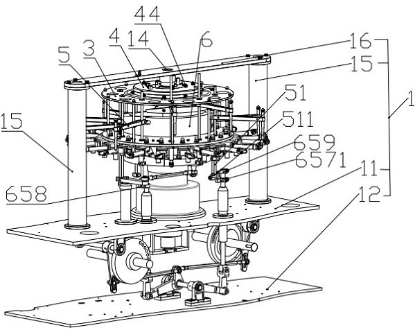
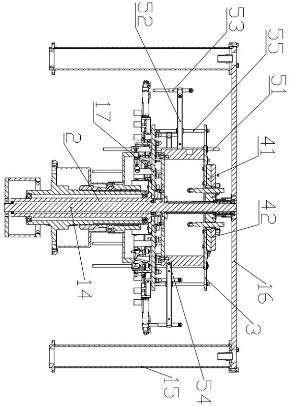
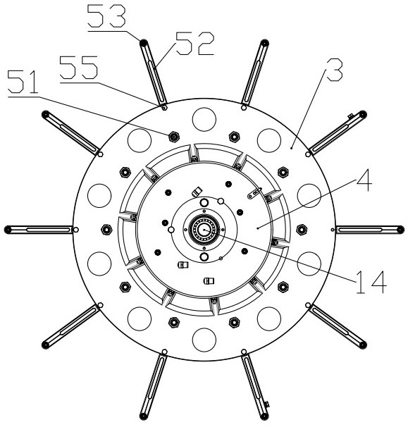
[0061]Embodiment 1, the drive mechanism 6 includes a first driving disk 61 and a first roller 62 located outside the outer peripheral surface of the first drive pan 61, the first driving disk 61 located below the first turntable 3 and One turntable 3 is set with axis, and the roller 54 is scrolled with the first roller groove 62, the first roller 62 penetrates in the circumferential direction and is provided with a low horizontal stroke one 621, high horizontal stroke one 622 and Connecting a low horizontal stroke one 621 and a high horizontal stroke one 622, a slope stroke one 623, the medium section of the slope stroke one is provided with a horizontal segment 624 for roller stay; when the mounting frame is rotated by the first turntable, The end roller scrolles in the first roller, the roller is inserted into the package into the package in the low-horizontal stroke, and the roller takes a high horizontal stroke along the ramp. One generation cannula has completed the gas. After ...
Embodiment 2
[0062]Embodiment 2, the drive mechanism 6 includes a second drive disk 63 and a second roller 64 located outside the outer peripheral surface of the second drive pan 63, the second drive disc 63 located below the first turntable 3 and A turntable 3 is disposed in an axis, and the roller 54 is rolled with the second roller 64, the second roller 64 penetrates in the circumferential direction and is provided with a low horizontal stroke 2 641, high horizontal stroke 2 642 and Two slopes 643 connecting low horizontal stroke 2 641 and high horizontal stroke 2 642, one of the intermediate sections of the ramp stroke 2 643 are disposed to split it into a vertical stroke 644 that is up and down, the vertical direction. The bottom end of the itinerary is available for the roller;
[0063]The drive mechanism 6 further includes a lifting assembly 65 for pushing the roller 54 from the bottom end and the top end of the vertical stroke 644, the lifting assembly 65 mounted on the frame 1 and is respe...
Embodiment 3
[0064]Example 3, the drive mechanism 6 includes:
[0065]The third drive disk 66; it is located below the first turntable 3 and is set to the first turntable 3;
[0066]The third roller 67 is disposed on the upper surface of the outer edge of the third drive disk 66;
[0067]The fourth drive plate 68 is located below the third drive disk 66 and is set to the first turntable 3;
[0068]The fourth roller 69 is located at the outer peripheral surface of the fourth drive pan 68, and the roller 54 is rolled with the fourth roller groove 69, and there is an opening 691 above both ends of the fourth roller 69. ;
[0069]The third drive disc can adjust the mounting of the upper and lower height on the central axis, and one end of the third roller is provided downwardly and corresponding to the opening corresponding to the opening; the third drive disk 66 and fourth The driving disk 68 is relatively stationary, the fourth drive pan 68 and the third drive disc 66 rotate relative to the first turntable 3, re...
PUM
 Abstract
Description
Claims
Application Information
 - R&D
- Intellectual Property
- Life Sciences
- Materials
- Tech Scout
- Unparalleled Data Quality
- Higher Quality Content
- 60% Fewer Hallucinations
Browse by: Latest US Patents, China's latest patents, Technical Efficacy Thesaurus, Application Domain, Technology Topic, Popular Technical Reports.
© 2025 PatSnap. All rights reserved.Legal|Privacy policy|Modern Slavery Act Transparency Statement|Sitemap|About US| Contact US: help@patsnap.com


