
Differential mechanism

A differential and speed technology, applied in the field of vehicles, can solve the problems of high differential speed, affecting the service life of the differential, and high temperature damage of the differential.

Pending Publication Date: 2021-05-25
SCHAEFFLER TECH AG & CO KG
View PDF0 Cites 0 Cited by
  • Summary
  • Abstract
  • Description
  • Claims
  • Application Information

AI Technical Summary

Problems solved by technology

[0003] However, the differential in the prior art has a situation where the rotational speed is too high
Excessive speed of the differential will cause the components of the differential to be in an excessively high ambient temperature, thereby causing the components of the differential to be damaged by high temperature, thereby affecting the service life of the differential

Method used


Image

  • Differential mechanism
  • Differential mechanism
  • Differential mechanism

Examples


Embodiment Construction

[0021] The specific implementation of the differential according to the present invention will be described below with reference to the accompanying drawings. The following detailed description and drawings are used to illustrate the principles of the present invention. The present invention is not limited to the described preferred embodiments, and the protection scope of the present invention is defined by the claims.

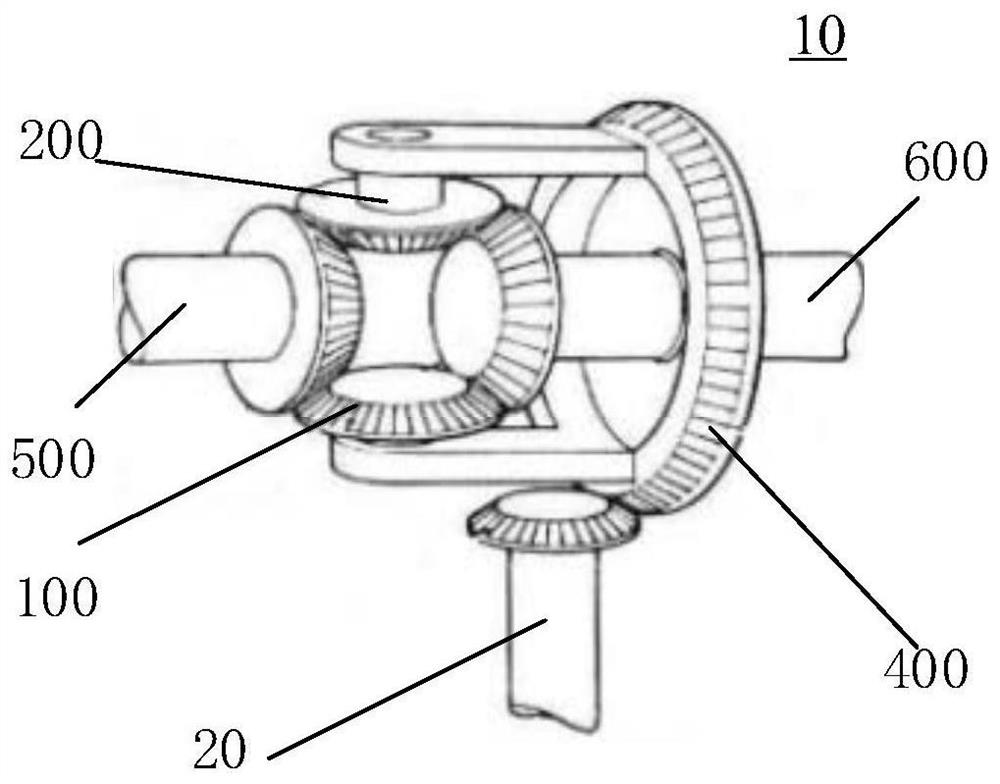
[0022] figure 1 A differential according to an embodiment of the invention is shown. Refer to the following figure 1 A differential according to an embodiment of the present invention is described.

[0023] Such as figure 1 As shown, the differential 10 includes two planetary gears 100 , a left side gear 500 , a right side gear 600 and a carrier 400 . The power is transmitted to the gear carrier 400 in the differential 10 through the input shaft 20, and the gear carrier 400 drives the two planetary gears 100 to rotate through the planetary gear shaft 200,...


PUM


Abstract

The invention relates to a differential mechanism which comprises a planetary gear and a planetary gear shaft. The planetary gear can rotate relative to the planetary gear shaft, the differential mechanism further comprises a speed limiting mechanism arranged on the planetary gear, and the speed limiting mechanism comprises an elastic element and a sliding block. When the rotating speed of the planetary gear is lower than the rotating speed threshold value, the sliding block slides on the planetary gear shaft at a first contact point on the first surface under the action of first elastic force and first centrifugal force applied by the elastic element, and when the rotating speed of the planetary gear is larger than the rotating speed threshold value, the sliding block slides on the planetary gear shaft at a second contact point on the first surface under the action of second elastic force and second centrifugal force applied by a spring element, the second contact point is closer to the edge of the first surface of the sliding block than the first contact point, so that the friction force generated when the sliding block makes contact with the planetary gear shaft through the second contact point is larger than the friction force generated when the sliding block makes contact with the planetary gear shaft through the first contact point.

Description

technical field [0001] The present invention relates to the field of vehicles, and in particular, to differentials in vehicles. Background technique [0002] During the running of the vehicle, the angular velocities of the left drive wheel and the right drive wheel are often not equal. In this case, if the vehicle does not have a differential and fixes the two drive wheels to the same rigid shaft, rolling and slipping must occur in the drive wheels. This phenomenon can lead to tire wear and loss of power, possibly even causing the vehicle to become unsteerable. Therefore, a differential is used in a vehicle to allow the vehicle to realize a differential speed between the left drive wheel and the right drive wheel when the vehicle travels non-straight, so that the vehicle travels normally. [0003] However, there is a situation that the rotational speed is too high in the differential gear in the prior art. Too high rotational speed of the differential will cause the compo...

Claims


Application Information

Patent Timeline
IPC IPC(8): F16H48/08F16H48/38F16H57/10F16D59/02
CPCF16D59/02F16H48/08F16H48/38F16H57/10
Inventor 翟青泉王坤
Owner SCHAEFFLER TECH AG & CO KG
Learn More