Glass unit having sliding groove and method for manufacturing same

A technology of glass and components, applied in the field of glass units with sliding grooves and used in the manufacture of glass units, which can solve problems such as difficulty in disassembly

Pending Publication Date: 2021-05-25
SAINT-GOBAIN GLASS FRANCE
View PDF2 Cites 0 Cited by
  • Summary
  • Abstract
  • Description
  • Claims
  • Application Information

AI Technical Summary

Problems solved by technology

Furthermore, this solution has the disadvantage that it is difficult to disassemble if it becomes necessary to replace one of the parts of the glass unit 1

Method used


Image

  • Glass unit having sliding groove and method for manufacturing same
  • Glass unit having sliding groove and method for manufacturing same
  • Glass unit having sliding groove and method for manufacturing same

Examples


Embodiment Construction

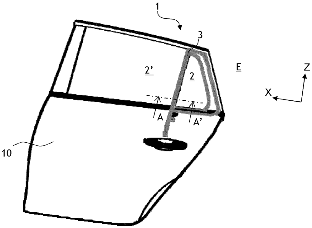
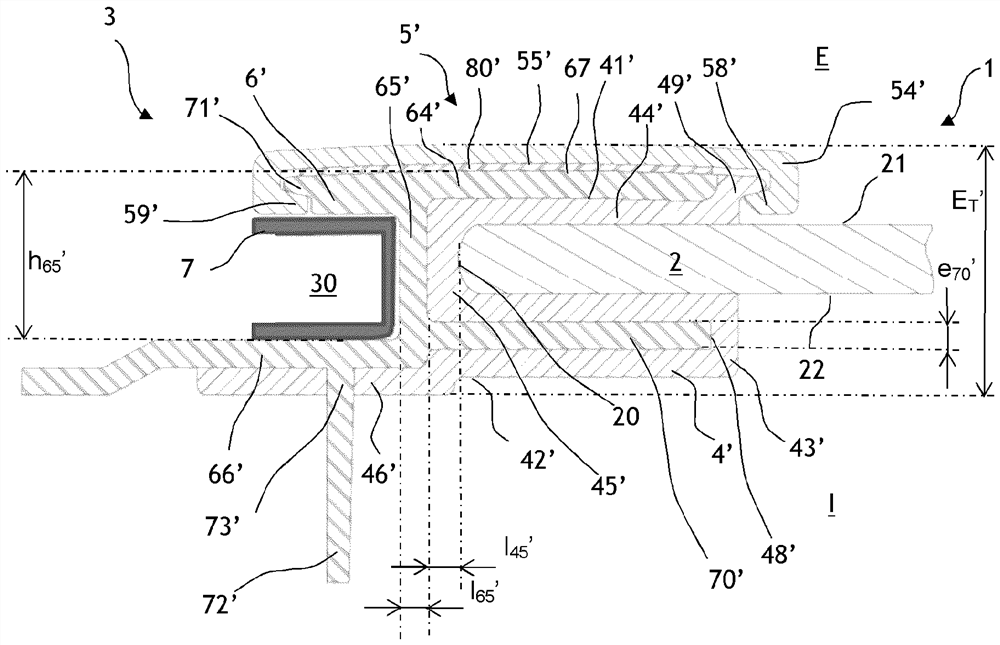
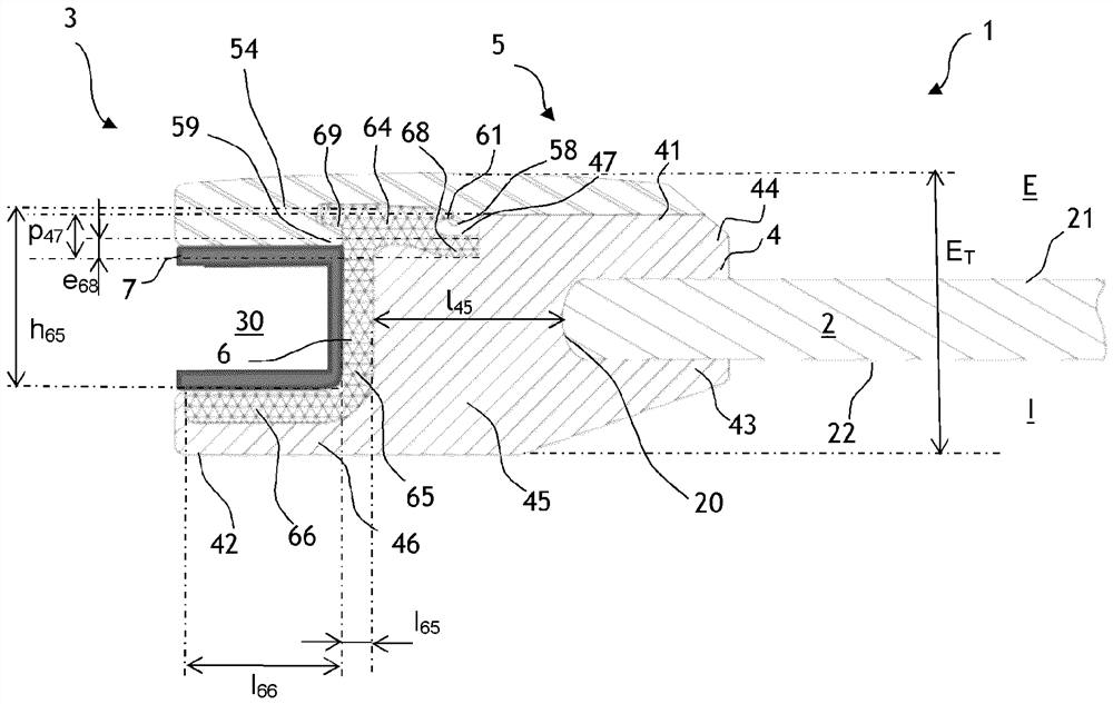
[0053] In these figures, individual elements in each figure are drawn to scale, but background elements are generally not shown in order to make the figures easier to study. Furthermore, for figure 1 , figure 2 and image 3 The reference numerals of the common elements are unchanged, and therefore these reference numerals remain the same in these figures. In the scope of this document, the concepts of "centripetal" and "central" should be figure 1 Considered in the plane of the sheet in , expressed along the X and Z axes relative to the center of the glass unit; the centripetal direction is towards this center and the centrifugal direction is away from this center.

[0054] The present invention relates to glass units 1, and in particular to figure 1 Vehicle glass unit as seen in . This glazing unit comprises a fixed glass element 2 forming a separation between the outer space E and the inner space I, and having an upright 3 sitting along the lateral edge of the fixed gl...


PUM


Abstract

The invention relates to a glass unit (1) comprising: a glass element (2); an upstanding portion (3) having a sliding groove (30) having a U-shape in cross section, and a forming strip (4) having a base (45) seated adjacent to an edge (20) of the glass element (2), the forming strip (4) having an intermediate reinforcing portion (6) having a body (65) and an inner arm (66), and the upstanding portion further having a covering portion (5). The covering portion (5) has a cover base plate (54) extending substantially perpendicular to the base (45), the intermediate reinforcing portion (6) is noticeable that it has an outer arm (64) extending from the body (65), and the cover portion (5) is noticeable that it has a proximal lug (58) and a distal lug (59).

Description

technical field [0001] The invention relates to a glazing unit (vitrage) comprising a fixed glazing element and comprising, along one lateral edge of said glazing element, a montant along a Extending laterally further outwards, the upright has a sliding groove, U-shaped in cross-section, for sliding the movable glass element therein, and: [0002] - On the one hand, there is a cordon profilé, which has: [0003] - a base, which sits adjacent to the edge of the glass element, and [0004] - an inner flange extending substantially perpendicular to said base and away from said glass element, and [0005] - said profiled strip has an intermediate reinforcing portion with: [0006] - a body situated opposite said edge of the glass element, wherein said base is interposed between said body and said edge, [0007] - and also having an inner arm extending substantially perpendicular to said body, extending further towards the inside than said body, and extending parallel to said i...

Claims


Application Information

Patent Timeline
IPC IPC(8): B60J10/265B60J10/78
CPCB60J10/265B60J10/78
Inventor L·拉穆勒X·德鲁埃M·博诺姆
Owner SAINT-GOBAIN GLASS FRANCE
Why Eureka
Try Eureka