
Cylinder body inner hole numerical control cylindrical coordinate chamfering machine

A technology of cylindrical coordinates and chamfering machines, which is applied to the parts of grinding machine tools, machine tools and grinding machines suitable for grinding the edge of workpieces, etc. It can solve the problems of manual chamfering without guarantee of quality, large and small chamfering, and high technical requirements. problem, to achieve the effect that the size of the chamfer will not be missed, the size of the chamfer is consistent, and the training cost is low

Pending Publication Date: 2021-05-28
山东瑞彬精密制造有限责任公司
View PDF0 Cites 0 Cited by
  • Summary
  • Abstract
  • Description
  • Claims
  • Application Information

AI Technical Summary

Problems solved by technology

[0002] In the production process of small air-cooled gasoline engine cylinders, the chamfering of cylinder scavenging passages and intake and exhaust passages is a major problem in the entire industry; no matter at home or abroad, there is no mechanized automatic chamfering equipment. At present, the entire All industries use manual chamfering; not only the quality of manual chamfering is not guaranteed, the chamfering can be large or small, and even omissions, but also labor-intensive and technically demanding. It takes a long time to train a qualified operator, and at the same time the efficiency is very high. Low

Method used


Image

  • Cylinder body inner hole numerical control cylindrical coordinate chamfering machine
  • Cylinder body inner hole numerical control cylindrical coordinate chamfering machine

Examples


Embodiment 1

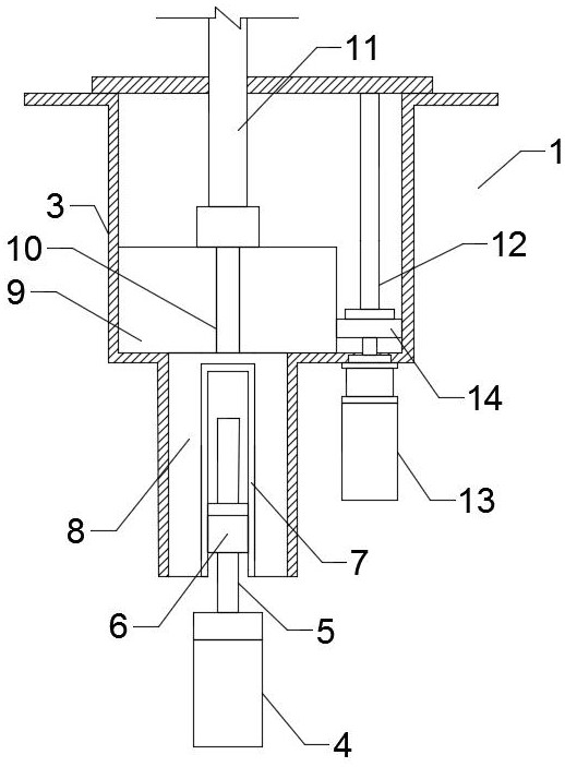
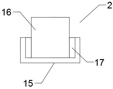
[0013] Such as Figure 1 to Figure 2 As shown, the present invention discloses a numerically controlled column coordinate chamfering machine for inner holes of cylinders. The technical solution adopted is to include a main machine 1, a grinding mechanism 2, and a numerically controlled operating system. The grinding mechanism 2 is connected to the main machine 1 and All are electrically connected with the numerical control operating system, the host 1 also includes a lower body 3, a Z-axis travel mechanism and an X-axis rotation mechanism, and the Z-axis travel mechanism also includes a Z-axis servo motor 4, a lead screw 5, a cylinder Pin 7, spline shaft 8, large gear 9 and main shaft 11, the output end of the Z-axis servo motor 4 is connected to the Z-axis reducer and then connected to the lead screw 5, and the screw nut 6 installed on the lead screw 5 is connected to the The cylindrical pin 7 is connected, the cylindrical pin 7 is connected to the spline shaft 8, and the spl...


PUM


Abstract

The invention discloses a cylinder body inner hole numerical control cylindrical coordinate chamfering machine. The numerical control cylindrical coordinate chamfering machine comprises a main machine, a grinding mechanism and a numerical control operating system. The main machine further comprises a lower machine body, a Z-axis advancing mechanism and an X-axis rotating mechanism, wherein a Z-axis servo motor of the Z-axis advancing mechanism is connected with a lead screw, a nut installed on the lead screw is connected with a cylindrical pin, the cylindrical pin is connected with a spline shaft, the spline shaft is located in the lower machine body, a mandrel is arranged above the spline shaft, a bull gear is arranged on the mandrel, and the upper part of the bull gear is connected with a main shaft; a X-axis servo motor of the X-axis rotating mechanism is connected with a small gear, and the small gear is engaged with the bull gear; and a grinding mechanism is arranged on the main shaft, the grinding mechanism further comprises a grinding head and a grinding head sleeve, the grinding head is connected into the grinding head sleeve through an expansion sleeve, and the grinding head sleeve is arranged on the main shaft. The Z-axis servo motor is used for controlling the lower machine body to move up and down, the X-axis servo motor is used for controlling the grinding mechanism to rotate, automatic chamfering can be achieved, chamfers are consistent in size and free of omission, the quality is uniform, and the training cost is low.

Description

technical field [0001] The invention relates to the field of machining cylinder hole wall chamfering, in particular to a numerically controlled column coordinate chamfering machine for cylinder inner holes. Background technique [0002] In the production process of small air-cooled gasoline engine cylinders, the chamfering of cylinder scavenging passages and intake and exhaust passages is a major problem in the entire industry; no matter at home or abroad, there is no mechanized automatic chamfering equipment. At present, the entire All industries use manual chamfering; not only the quality of manual chamfering is not guaranteed, the chamfering can be large or small, and even omissions, but also labor-intensive and technically demanding. It takes a long time to train a qualified operator, and at the same time the efficiency is very high. Low. Contents of the invention [0003] In view of the problems existing in the prior art, the present invention discloses a numerically...

Claims


Application Information

Patent Timeline
IPC IPC(8): B24B9/00B24B47/12
CPCB24B9/00B24B47/12
Inventor 张雪凝张兆亮张守联
Owner 山东瑞彬精密制造有限责任公司
Learn More