Pipe fitting servo chamfering machine

A technology of chamfering machine and pipe fittings, which is applied in metal processing machinery parts, manufacturing tools, metal processing, etc., can solve the problems of low equipment utilization, low processing precision, and low production efficiency, and achieve low cost, simple structure, and simplified The effect of equipment

Pending Publication Date: 2018-11-23
广东志达精密管业制造股份有限公司
View PDF7 Cites 0 Cited by
  • Summary
  • Abstract
  • Description
  • Claims
  • Application Information

AI Technical Summary

Problems solved by technology

[0002] At present, domestic steel pipe manufacturers usually use hydraulic or pneumatic double-head chamfering machines to process the end face chamfering of steel pipes. This type of processing method has the disadvantages of low processing accuracy, troublesome adjustment, low equipment utilization rate, and low production efficiency.

Method used


Image

  • Pipe fitting servo chamfering machine
  • Pipe fitting servo chamfering machine
  • Pipe fitting servo chamfering machine

Examples


Embodiment Construction

[0033] The technical solutions of the present invention will be described below in conjunction with the accompanying drawings of the present invention.

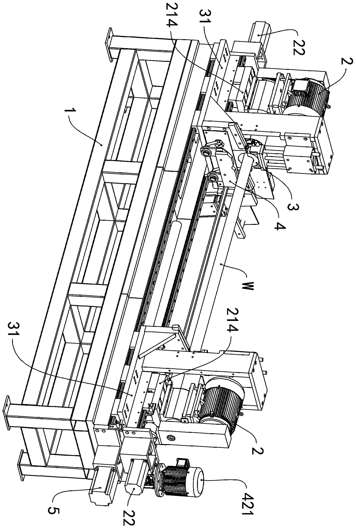
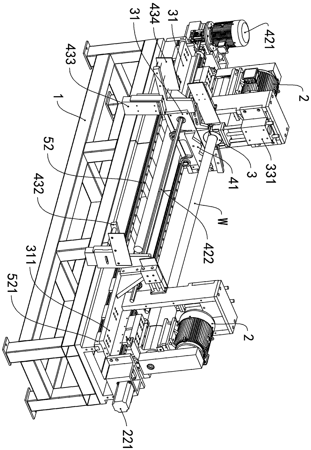
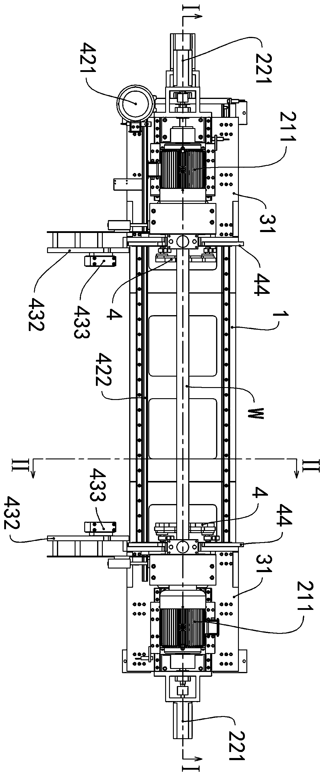
[0034] A servo chamfering machine for pipe fittings of the present invention comprises a frame 1 , two chamfering devices 2 , and two clamping devices 3 ;

[0035] The chamfering device 2 is a powered tool for the end of the chip pipe W. For example, the chamfering device 2 includes a chamfering cutterhead 21, a chamfering motor 211, a transmission member 212, a chamfering power head 213, a cutterhead base 214 and Feed device 22, the rotary output end of chamfering motor 211 is connected with chamfering power head 213 by transmission part 212, and chamfering motor 211, chamfering power head 213 are all arranged on the cutter head base 214, and chamfering cutter head 21 and The chamfering power head 213 is fixedly connected, and the chamfering power head 213 is hinged with the cutterhead base 214; the feed device 22 includes a...


PUM


Abstract

The invention relates to the technical field of steel pipe processing and production, in particular to a pipe fitting servo chamfering machine, which comprises a frame, two lead angle devices and twoclamping devices; the lead angle devices and the clamping devices are all arranged on the frame. The pipe servo chamfering machine also comprises two pipe conveying devices, wherein the two pipe conveying devices are respectively connected with two clamping devices; the pipe conveying device comprises a pipe conveying plate and a conveying rotating device, wherein the conveying rotating device isarranged on the clamping device. The pipe conveying plate is hinged horizontally to the rotary output end of the conveying rotary device, and is provided with an inlet pipe notch and an outlet pipe notch. The pipe servo chamfering machine has the advantages of continuously and automatically completing the chamfering of the pipe fitting, simple structure, low cost, high reliability, and automatically conveying the pipe fitting to the inlet pipe notch.

Description

technical field [0001] The invention relates to the technical field of steel pipe processing and production, in particular to a pipe fitting servo chamfering machine. Background technique [0002] At present, domestic steel pipe manufacturers usually use hydraulic or pneumatic double-head chamfering machines to process the end face chamfering of steel pipes. This type of processing method has the disadvantages of low processing accuracy, troublesome adjustment, low equipment utilization rate, and low production efficiency. [0003] In order to improve the chamfering efficiency of the end face of long pipes, there is an urgent need for an automatic device that can quickly adjust and chamfer. Contents of the invention [0004] To solve the above problems, the object of the present invention is to provide a pipe fitting servo chamfering machine, which can continuously and automatically complete the chamfering of pipe fittings W. [0005] The detailed technical solution adopt...

Claims


Application Information

Patent Timeline
Patent Type & Authority Applications(China)
IPC IPC(8): B23D79/00B23Q5/40B23Q3/06B23Q7/00
CPCB23D79/00B23Q3/064B23Q5/40B23Q7/00
Inventor 伍伦春罗立新
Owner 广东志达精密管业制造股份有限公司
Why Eureka
Try Eureka