Electrofusion pipe-fitting joining system and method utilizing conductive polymeric resin

a technology of conductive polymeric resin and pipe fittings, which is applied in the field of electrofusion pipe fittings joining systems and methods utilizing conductive polymeric resin, and pipe fitting methods using electrofusion, can solve the problems of human induced errors in fabrication and handling, high cost, and inability to meet the requirements of use, and achieve the effect of reducing the number of pipe fittings

Inactive Publication Date: 2006-01-26
GEORGE FISCHER SLOANE
View PDF22 Cites 43 Cited by
  • Summary
  • Abstract
  • Description
  • Claims
  • Application Information

AI Technical Summary

Problems solved by technology

The current manufacturing methods in producing this “coil” are expensive, labor intensive and subject to human induced errors in fabrication and handling.
Moreover, current electrofusion joining methods that utilize wire may introduce contamination, particularly from the wire, into the fluid being conveyed in the piping system.
Electrofusion joining methods that utilize wire may also cause wire movement that may affect the integrity of the formed joint.
The heating also causes fusion.
However, this particular embodiment is directed to a cable where the heating element is used to cause a heat shrink layer to shrink (and is not used for electro-fusion).

Method used


Image

  • Electrofusion pipe-fitting joining system and method utilizing conductive polymeric resin
  • Electrofusion pipe-fitting joining system and method utilizing conductive polymeric resin
  • Electrofusion pipe-fitting joining system and method utilizing conductive polymeric resin

Examples


Embodiment Construction

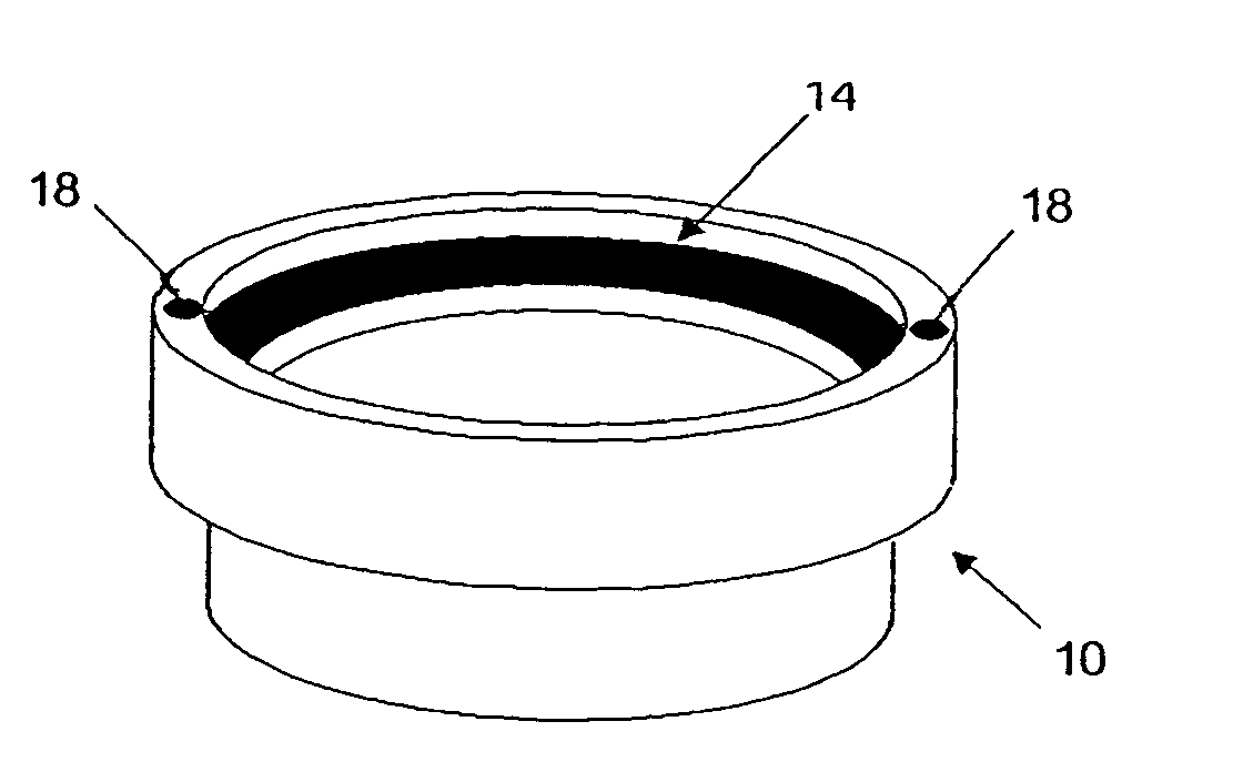
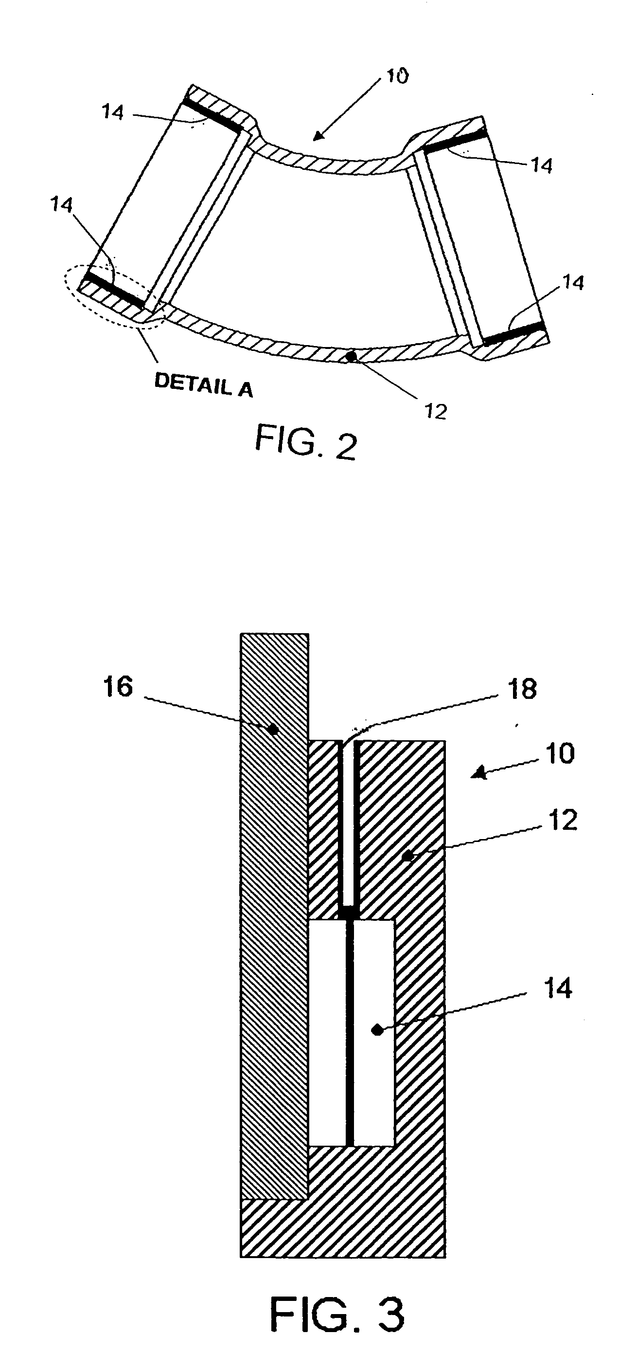
[0034] The present invention is directed to electrically conductive plastics in which a blend of plastic resin and conductive substrate (the conductive polymer composite material) is injection molded, for example, co-injection molded, into an appropriate shape for the purpose of fusion of two or more plastic components (such as an end of a pipe to a pipe fitting). Electrical current is passed through the conductive polymer composite material whereby resistance caused in the conductive polymer composite material heats and thereby fuses the two or more plastic components. The conductive polymer composite material is placed between the components being fused and is in the form of a collar. Variations may be made, for example, in the percent concentration of conductive materials (such as nano-conductive materials) present in the composite material, and the dielectric properties of the composite material. A higher percentage of conductive material in the composite material creates a lowe...


PUM

PropertyMeasurementUnit
outer diameteraaaaaaaaaa

Abstract

A joining device for electrofusion of at least one end of a pipe to a fitting is provided which includes a fitting of a polymeric material and a collar adapted to receive the end of the pipe. The collar is fabricated from a conductive polymer composite material and positioned within the fitting. A connector for connecting the collar to a source of current may be provided which may be integral to the fitting. Likewise, the collar may be integral to the fitting. All three of the connector, collar and fitting are preferably an integral unit. A method of making the joining device and a method of using the joining device are also provided.

Description

BACKGROUND OF THE INVENTION [0001] The present invention is generally directed to pipe joining methods. More particularly, the present invention is directed to pipe joining methods using electrofusion. [0002] In the prior art, pipe fitting joining methods using electrofusion have utilized solid wire as a conductor to provide resistance heating. This wire is wound in various configurations such that the wire may be properly inserted in a pipe / fitting interface. FIG. 1A depicts one example of such a resistance wire. FIG. 1B shows the resistance wire of FIG. 1A as applied to a pipe connector. The current manufacturing methods in producing this “coil” are expensive, labor intensive and subject to human induced errors in fabrication and handling. [0003] Moreover, current electrofusion joining methods that utilize wire may introduce contamination, particularly from the wire, into the fluid being conveyed in the piping system. [0004] Electrofusion joining methods that utilize wire may also...

Claims


Application Information

Patent Timeline
Patent Type & Authority Applications(United States)
IPC IPC(8): B32B37/00
CPCB29C45/14B29C66/1224B29C65/342B29C65/3488B29C65/362B29C66/5221B29D23/005B29K2995/0005B82Y30/00F16L47/03B29C65/3468B29C65/3492B29C66/52211B29C66/5223B29C65/3684B29C66/5229B29C66/52292B29C66/1222B29C45/16B29C66/1122B29C66/71B29C66/7315B29C66/7392B29K2995/0089B29K2077/00B29K2023/10B29K2027/06B29K2027/16B29K2023/12B29K2023/06
Inventor BARBONE, RICCARDO E.MASTRO, PAUL F.GILCHRIST, JAMES
Owner GEORGE FISCHER SLOANE
Why Eureka
Try Eureka