Automatic workpiece chamfering equipment and control method

A workpiece and chamfering technology, which is applied to the special processing equipment for workpiece chamfering and its control field, can solve the problems of high labor intensity, low production efficiency, long chamfering cycle, etc., and achieves a high degree of intelligence, convenient operation, simple structure

Pending Publication Date: 2018-02-27
FOSHAN NANHAI GUANGDONG TECH UNIV CNC EQUIP COOP INNOVATION INST +1
View PDF0 Cites 9 Cited by
  • Summary
  • Abstract
  • Description
  • Claims
  • Application Information

AI Technical Summary

Problems solved by technology

[0002] At present, most of the chamfering in factories uses hand-held finished products to chamfer on the grinder. The labor intensity is high, the working environment is harsh, and it is easy to cause work-related injuries to the human body; Multiple transformations are performed, the chamfering cycle is long, and the production efficiency is not high

Method used


Image

  • Automatic workpiece chamfering equipment and control method
  • Automatic workpiece chamfering equipment and control method

Examples


Embodiment 1

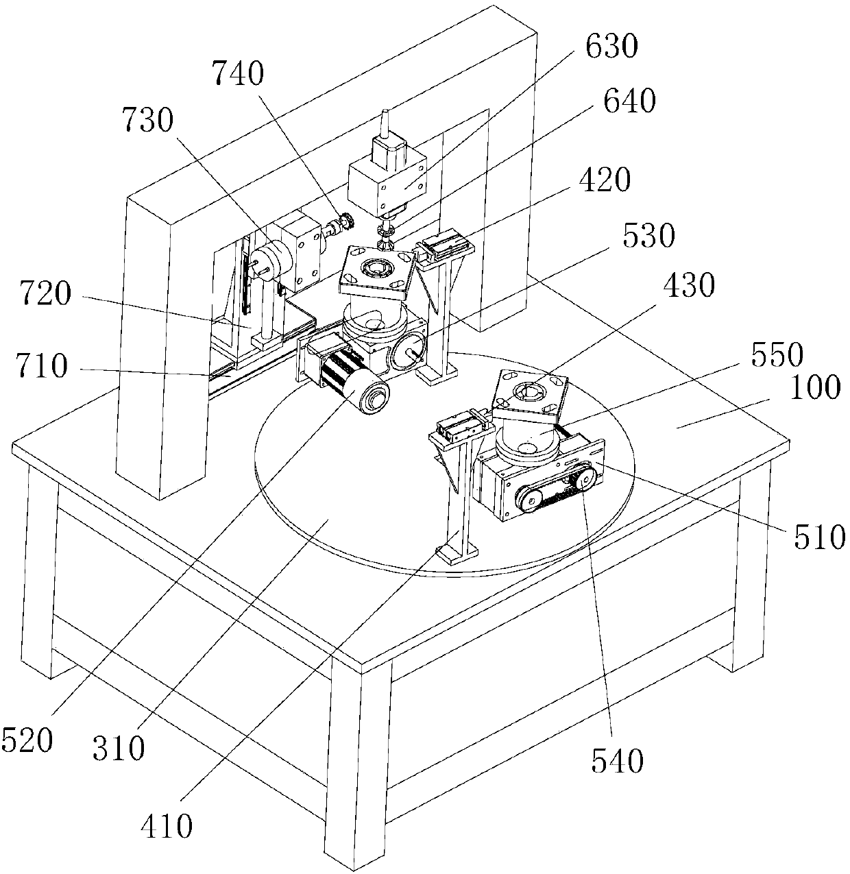
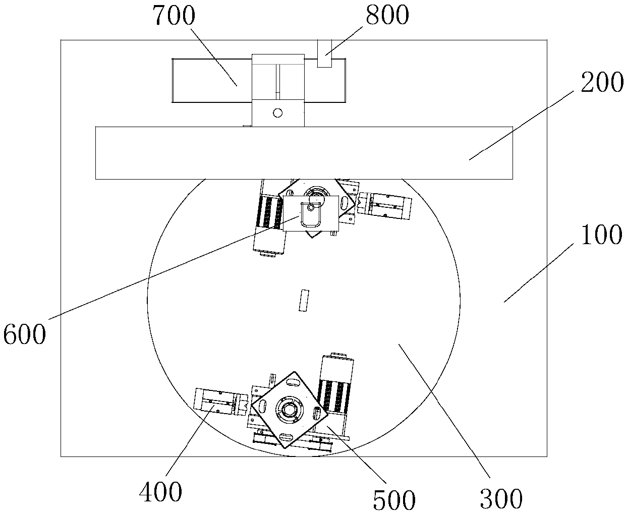
[0039] Such as figure 1 and figure 2 As shown, the present invention discloses a workpiece automatic chamfering equipment, which mainly includes a workbench 100, a gantry 200 arranged on the workbench 100, a conversion table 300 for loading and unloading, and a positioning device for correcting the position of the workpiece. The mechanism 400, the locking mechanism 500 for fixing the position of the workpiece, the first chamfering mechanism 600 for chamfering the R corner of the workpiece, and the second chamfering mechanism 700 for chamfering the edge of the workpiece. Both the locking mechanism 500 and the positioning mechanism 400 are fixed on the conversion table 300, and the conversion table 300 is installed on the workbench 100, and rotated to the chamfering station with the locking mechanism 500 and the positioning mechanism 400 for processing. The gantry 200 is installed on the workbench 100 and is located on one side of the conversion platform 300 . The first chamf...

Embodiment 2

[0060] This embodiment discloses a special machine for workpiece chamfering, including: a workbench 100; a double-station transfer table 300 installed directly above the workbench 100; a gantry 200 installed above the workbench 100 and One side of the double station transfer table 300; two workpiece positioning mechanisms 400 symmetrically installed on the double workpiece transfer table 300; a laser detection mechanism installed on the right side of the workpiece positioning mechanism 400, and the laser detection mechanism is installed on the working On the platform 100; the edge chamfering mechanism installed directly in front of the gantry 200; the chamfering R angle mechanism installed directly behind the gantry 200;

[0061] In the above technical solution, the workpiece to be chamfered is placed in the workpiece positioning mechanism 400 manually or by a robot, and the double-station transfer table 300 installed on the workbench 100 rotates 180 degrees to transfer the wor...


PUM


Abstract

The invention discloses automatic workpiece chamfering equipment and a control method. The automatic workpiece chamfering equipment comprises a workbench, a portal frame, a conversion table, a positioning mechanism, a locking mechanism, a first chamfering mechanism and a second chamfering mechanism. Firstly, a workpiece is placed on a hydraulic chuck, and a positioning air cylinder and the hydraulic chuck conduct positioning and locking on the position of the workpiece; then, a rotary disc conveys the workpiece to a chamfering station; then, the first chamfering mechanism conducts R angle chamfering on the edge of the workpiece; then, the second chamfering mechanism conducts chamfering on each edge of the workpiece; and finally, a first motor acts and drives the rotary disc to rotate by 180 degrees again, a to-be-machined workpiece is conveyed to the chamfering station to the machined, the machined workpiece is conveyed to a feeding station, unloading and loading operation is conducted, the process is operated in a full automation manner, manual intervention is not needed, and an alarm can be given for warning when the fault happens or positioning is inaccurate, and accordingly theworkpiece chamfering efficiency and quality are improved. The automatic workpiece chamfering equipment and the control method have the beneficial effects that the structure is simple, manufacturing is easy, control precision is high, and operation is convenient.

Description

technical field [0001] The invention relates to the field of machining equipment, in particular to a special machining equipment for workpiece chamfering and a control method thereof. Background technique [0002] At present, most of the chamfering in factories uses hand-held finished products to chamfer on the grinder. The labor intensity is high, the working environment is harsh, and it is easy to cause work-related injuries to the human body; Multiple transformations are performed, the chamfering cycle is long, and the production efficiency is not high. [0003] Therefore, the prior art needs to be further improved and perfected. Contents of the invention [0004] The purpose of the present invention is to overcome the deficiencies of the prior art and provide an automatic chamfering device with simple structure and high efficiency. [0005] Another object of the present invention is to overcome the shortcomings of the prior art and provide a control method based on t...

Claims


Application Information

Patent Timeline
Patent Type & Authority Applications(China)
IPC IPC(8): B23C3/12
CPCB23C3/126
Inventor 王斌谢克庆
Owner FOSHAN NANHAI GUANGDONG TECH UNIV CNC EQUIP COOP INNOVATION INST
Why Eureka
Try Eureka