Printing device and method and printer

A technology for printing devices and printing media, applied in printing devices, printing and printing of special varieties of printed matter, can solve the problems of narrow application range of RFID tags, inaccurate reading and writing, complicated operation, etc., and achieve simple structure, easy reading and writing Accurate, easy-to-operate results

Active Publication Date: 2021-05-28
重庆打贴匠科技有限公司
10 Cites 0 Cited by

AI-Extracted Technical Summary

Problems solved by technology

[0004] In view of the shortcomings of the prior art described above, the purpose of the present invention is to provide a printing device, method and printe...

Method used

Optionally, the second antenna radiating unit is limited by the length of the monopole antenna body. In order to reach the corresponding frequency range, it has undergone multiple bendings. The number of times of bending and the spacing can be determined by pre-testing. After bending The monopole antenna can have a certain radiation direction on the ozx plane, so that the monopole antenna can more accurately detect the radio frequency information writing state of the printing medium.
Referring to Fig. 11 and Fig. 12, shown in Fig. 11 and Fig. 12 is the radiation pattern of monopole antenna shown in Fig. 9 in ozx and ozy plane, from the combination of two figures, this monopole The radiation pattern of the antenna covers a wide range and has a certain omnidirectionality. The gain of the antenna is about 2dBi, which can meet the requirem...

Abstract

The invention provides a printing device and method and a printer. The device comprises a printing transmission mechanism which is used for inputting a printing medium comprising a radio frequency identification tag, a printing unit which is used for conducting printing on the printing surface of the printing medium in a target printing area, and a radio frequency tag read-write execution which is arranged at one side, close to the printing surface, of the printing unit and used for reading and writing the radio frequency identification tag in the printing medium, and the printing transmission mechanism is further used for conveying the printing medium in the target printing area to leave the printing unit if printing and reading and writing of the radio frequency identification tag are completed. In the printing process, due to the fact that the distance between the radio frequency tag read-write execution unit and the radio frequency identification tag in the printing medium is very close, it can be guaranteed that the radio frequency tag read-write execution unit can only conduct radio frequency information read-write with the radio frequency identification tag in the printing medium to be printed currently in the radio frequency information read-write execution process, and therefore the problems of excessive reading, misreading or incapability of reading are solved, reading and writing are more accurate, meanwhile, the printing device and method and the printer can be suitable for various types of RFID tags, operation is easy and convenient, and the structure is simple.

Application Domain

Pattern printingTypewriters +1

Technology Topic

Radio frequencyMechanical engineering +3

Image

  • Printing device and method and printer
  • Printing device and method and printer
  • Printing device and method and printer

Examples

  • Experimental program(2)

Example Embodiment

[0053] Embodiment one
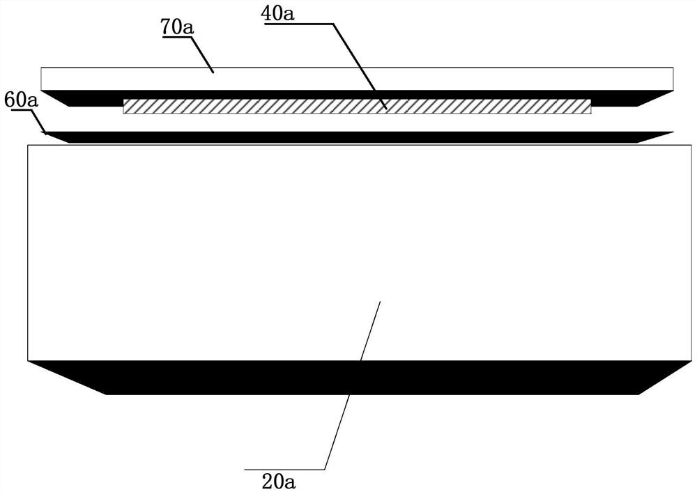
[0054] see figure 1 , an embodiment of the present invention provides a printing device, including:
[0055] The printing transmission mechanism 20a is used to convey the printing medium 60a including the radio frequency identification label, and the printing medium includes several sections of printing areas;
[0056] A printing unit 70a, configured to print on the printing surface of the printing medium 60a in the target printing area;
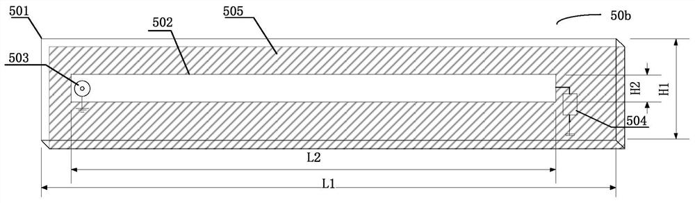
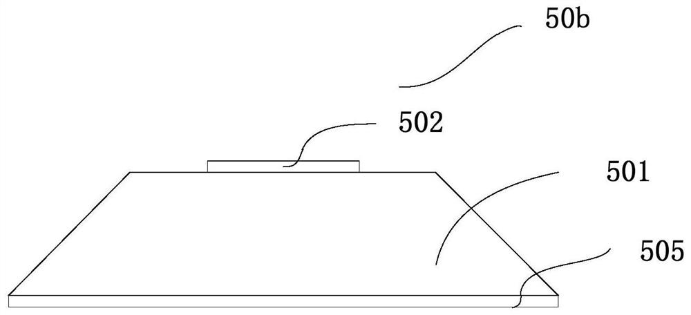
[0057] The radio frequency tag reading and writing execution unit 50a is arranged on the side of the printing unit 70a close to the printing surface, and is used to read and write the radio frequency identification tag in the printing medium;
[0058] The printing transmission mechanism is also used for sending the printing medium in the target printing area away from the printing unit if the printing and reading and writing of the radio frequency identification label are completed. Optionally, the radio frequency identification label is provided with an RFID chip, and the printing medium can be thermal printing paper, etc., and relevant characters, symbols, patterns, two-dimensional codes, etc. can be printed on the surface of the printing medium through the printing unit.
[0059] Optionally, the printing unit includes but is not limited to a thermal transfer printing head, and the printing unit can print relevant information on the surface of the printing medium according to the received printing information.
[0060] Optionally, the print information may be obtained through human-computer interaction devices such as keyboards and touch screens. The printing information can also be obtained through the information receiving device provided by the printing device to obtain relevant printing information transmitted over the network, such as transmitting the printing information to the printing device through WiFi, Bluetooth, 5G network, etc. The printing information can also be obtained by reading the information stored in the computer-readable storage medium by the printing device, for example, by reading the information in the USB flash drive connected through communication as the printing information and the like.
[0061] Optionally, the printing transmission mechanism transports the printing medium according to a preset order, such as the physical arrangement order of the printing areas on the printing medium, and the printing area currently on the printing platform corresponding to the printing unit is also the target printing area At this time, the printing unit can print on the printing surface of the target printing area.
[0062] Optionally, the completion of printing can be judged by relevant technical means in the field, which is not limited here.
[0063] Optionally, the completion of reading and writing of the radio frequency identification tag can also be judged by related technical means in the field, which is not limited here.
[0064] Optionally, radio frequency identification tags are included in each printing area.
[0065] Sometimes, the RFID tag is not completely covered in the printing area, because the printing unit may require a certain displacement of the printing medium to complete the printing when performing the printing operation. At this time, the RFID tag reading and writing execution unit can The positional relationship between the tag and the radio frequency tag reading and writing execution unit is determined to determine the best reading and writing position, and the radio frequency identification tag is read and written.
[0066] Optional, continue to see figure 1 , the radio frequency tag reading and writing execution unit is arranged on the print head side of the printing unit, which can realize that the radio frequency tag reading and writing execution unit reads and writes the radio frequency identification tag in the printing medium when the printing unit is close to the printing surface for printing, thus The two dimensions of printing on the printing surface and reading and writing of radio frequency identification tags can be realized based on the fact that the printing medium is at the same position.
[0067] Optionally, if the printing on the printing surface is completed and the reading and writing of the radio frequency identification tag is also completed, the printing transmission mechanism is also used to transport the printing medium that has been printed on the printing surface and the reading and writing of the RFID tag away from the printing unit.
[0068] Optionally, the preset read-write distance range can be set by those skilled in the art as required.
[0069] Optionally, the radio frequency tag reading and writing execution unit is configured to read and write the radio frequency identification tag in the printing medium when the reading and writing distance is within the preset reading and writing distance range, and the reading and writing distance includes the side of the printing unit close to the printing surface The distance from the printing surface.
[0070] Optionally, since the radio frequency tag reading and writing execution unit is arranged on the side of the printing unit close to the printing surface, the distance between the side of the printing unit near the printing surface and the printing surface can be approximately understood as the distance between the radio frequency tag reading and writing execution unit and the radio frequency identification tag Therefore, based on the relationship between the reading and writing distance and the preset reading and writing distance range, the radio frequency tag reading and writing execution unit can be controlled to read and write the radio frequency identification tag in the printing medium.
[0071] Optionally, when the printing unit prints on the printing surface, the distance between the printing unit and the printing surface tends to be shortened (it may be that the printing unit falls to the printing surface, or the printing medium is lifted toward the printing unit, etc.), In the printing process, the radio frequency tag reading and writing execution unit is controlled to read and write the radio frequency identification tag in the printing medium, and the reading and writing distance can also be controlled to be within the preset reading and writing distance range before or after printing, so as to control the radio frequency The tag reading and writing execution unit reads and writes the radio frequency identification tags in the printing medium. Optionally, the printing medium includes several sections of printing areas, and the printing transmission mechanism sequentially transports the printing media according to the preset order of the printing areas. The transporting may be transporting unprinted printing media to the printing unit for printing (forward transport ), it is also possible to reversely transport the printing medium leaving the printing unit after printing to the printing unit or the upstream position of the printing unit (returning).
[0072] by figure 1 For example, the radio frequency tag reading and writing execution unit 50a is arranged at the lower part of the printing unit 70a. When performing a printing operation, the platen roller corresponding to the printing unit will guide the printing unit to the printing medium that currently needs to be printed. When the RFID tag in the printing medium is located under the RFID tag reading and writing execution unit, the distance between the RFID tag reading and writing execution unit and the RFID tag is very close during the printing process, which is much smaller than the working wavelength of the RFID tag. Therefore, on the one hand, the RFID tag The read-write execution unit can transmit information with the radio frequency identification tag through the induction field. Information transfer is carried out with RFID tags in other nearby printing media, so it is guaranteed that there will be no problems of over-reading, misreading or failing to read RFID tags. Taking the radio frequency identification tag as an example of an electronic tag in the UHF frequency band, its frequency range is between 840MHz and 960MHz, and the frequency range for China is between 920MHz and 925MHz. The working wavelength of the radio frequency identification tag is λ=c/f= 324-326mm, which is much larger than the distance between the RFID tag and the RFID tag reading and writing execution unit during the printing process.
[0073] In some examples, see figure 2 , the radio frequency tag reading and writing execution unit 50a includes a microstrip antenna 50b;
[0074] The microstrip antenna 50b includes a first antenna radiating unit 502, a first substrate 501, and a first ground plate 505 from top to bottom, and the microstrip antenna 50b also includes a first coaxial line access terminal 503 and an absorption resistor 504. One end of the axis access terminal 503 is connected to the feeding point of the first antenna radiation unit 502, the other end of the first coaxial line access terminal 503 is connected to the first ground plate 505, and one end of the absorption resistor 504 is connected to the first antenna radiation The end of the unit 502 and the other end of the snubber resistor 504 are connected to the first ground plate 505 .
[0075] Optionally, the first antenna radiating unit is located within the area where the upper surface of the first ground plate is located, that is, the length L2 and width H2 of the first antenna radiating unit of the microstrip line antenna are both smaller than the length of the first substrate below it L1 and the width H1 of the first substrate.
[0076] In some embodiments, see continuing figure 2 , the microstrip antenna 50b includes a first substrate 501 , a first antenna radiating element 502 , a first coaxial line access terminal 503 , a snubber resistor 504 and a first ground plate 505 . Wherein the first substrate 501 is a cuboid, length L1=118mm, width H1=5mm, thickness=0.4mm, microstrip antenna 50b is formed by pressing three parts, the top surface is the first antenna radiation unit 502, length L2=85mm , width H2 = 3 mm, the middle is the first substrate 501 , and the bottom is the first ground plate 505 . The first coaxial line access terminal 503 may be a dual-port device, one end is connected to the feeding point of the first antenna radiation unit 502 , and the other end is connected to the first ground plate 505 . One end of the absorption resistor 504 is connected to the end of the first antenna radiation unit 502 , and the other end is connected to the first ground plate 505 . It should be noted that the above-mentioned length and width of the first substrate and the length and width of the first antenna radiating unit are only examples, and those skilled in the art can also select a microstrip antenna with appropriate specifications according to the specifications of commonly used printing media. .
[0077] Optionally, the material of the first antenna radiating unit includes but is not limited to 1oz copper clad laminate with a thickness of 35um; the first substrate includes but is not limited to FR4 dielectric substrate; the bottom surface of the first substrate is provided with an entire surface of copper foil as First ground plate.
[0078] Optionally, the microstrip antenna can also be in other shapes, and those skilled in the art can set it according to needs, for example, see image 3 , the first substrate 501 of the microstrip antenna 50b has a three-dimensional shape with a narrow top and a wide bottom. At this time, by increasing the contact area between the microstrip antenna and the printing unit, the fixing strength of the microstrip antenna can be increased to improve the stability of the structure.
[0079] see Figure 4 , Figure 4 for figure 2 The reflection coefficient of the microstrip antenna shown (S 11 ) as a function of frequency, from Figure 4 It can be obtained that the -10dB bandwidth of the microstrip antenna is between 810MHz and 950MHz.
[0080] see Figure 5 , Figure 5 for figure 2 The radiation pattern of the ozx plane of the microstrip antenna shown, it can be seen that the microstrip antenna has a certain directionality.
[0081] see Image 6 , Image 6 for figure 2 The radiation pattern of the ozy plane of the microstrip antenna shown, since the structure of the microstrip antenna is symmetrical on the ozy plane, so from Image 6 It can be seen that the microstrip antenna has good symmetry.
[0082] Optionally, by setting the absorption resistor in the microstrip antenna, the return loss can be greatly reduced, the interference of reflection to the read-write module can be reduced, and the reliability of the product can be greatly improved.
[0083] In some examples, see Figure 7 and Figure 8 , Figure 7 is a schematic diagram of the front structure of the printing device, Figure 8 It is a schematic diagram of the side structure of the printing device, and the printing device also includes:
[0084] The radio frequency label detection execution unit 40a is arranged on at least one of the left side or the right side of the printing transmission mechanism 20a, and is used to detect the radio frequency information writing status of the printing medium 50a leaving the printing unit 70a.
[0085] Optionally, the printing device may include one or more radio frequency tag detection execution units, and the radio frequency tag detection execution unit may be as Figure 7 As shown, it is arranged on the left side of the printing transmission mechanism, it can also be arranged on the right side of the printing transmission mechanism, and it can also be arranged on the left and right sides of the printing transmission mechanism.
[0086] Optionally, the radio frequency label detection execution unit can be connected with the printing transmission mechanism through a bracket to form an integral structure, or can form a separate structure with the printing transmission mechanism through other fixed structures.
[0087] optional, see Figure 8 The radio frequency tag detection execution unit 40a is arranged on one side of the printing medium output direction of the printing device, so that the radio frequency information writing state of the printed printing medium can be better detected by the radio frequency tag detection execution unit.
[0088] Optionally, in order to save resources and reduce interference to the radio frequency tag reading and writing execution unit, the top of the radio frequency tag detection execution unit is not higher than the top surface of the printing transmission mechanism, in other words, the top of the radio frequency tag detection execution unit is not higher than The print media currently being printed.
[0089] Optionally, sometimes the output printed printing medium may be bent to a certain extent. At this time, in order to ensure the accuracy of the detection of the radio frequency information writing status of the printing medium leaving the printing unit, the antenna of the radio frequency label detection execution unit can be enlarged The width along the output direction of the printing medium.
[0090] Optionally, the radio frequency label detection execution unit simultaneously detects the radio frequency information writing status of several printing media leaving the printing unit.
[0091] Optionally, the radio frequency label detection execution unit can be set to start detection at intervals according to the printing speed, which can save resources and reduce energy consumption. For example, if the printing speed is 2 print media per minute, the radio frequency tag detection execution unit can simultaneously detect at least 4 print media at a time. At this time, the radio frequency tag detection execution unit can start detection every two minutes.
[0092] In some examples, see Figure 9 The radio frequency tag detection execution unit includes a monopole antenna, and the monopole antenna includes a second coaxial line intervening terminal 404, a second substrate 401, a second antenna radiating unit 403, and a second connector disposed at one end of the second substrate 403. floor 402;
[0093] One end of the second coaxial line insertion terminal 404 is connected to the feeding point of the second antenna radiation unit 403, and the other end of the second coaxial line insertion terminal 404 is connected to the second grounding plate 402;
[0094] The second antenna radiating unit 403 is staggered and bent and disposed on the top surface of the second substrate 401 .
[0095] Optional, continue to see Figure 9 , if the second substrate is in the shape of a cuboid, its length L3=80mm, its width H3=10mm, and its thickness=0.6mm, the monopole antenna is formed by pressing two parts (the second substrate and the second antenna radiation unit), and the top The surface is the second antenna radiation unit 403, the length L4=64mm, the width H3=10mm, and the second grounding plate 402, the length L5=15mm, the width H3=10mm. Optionally, the second grounding plate can use a 1oz copper-clad board , and its thickness is 35um. Optionally, the second substrate on the bottom surface may be an FR4 dielectric substrate. The second coaxial line access terminal 404 is a two-port device, one end of which is connected to the feeding point of the second antenna radiation unit 403 , and the other end is connected to the second ground plate 402 .
[0096] see Figure 10 , Figure 10 for Figure 9 The graph of the reflection coefficient (S11) of the monopole antenna shown as a function of frequency, from Figure 10 It is obtained that the monopole antenna has a very small reflection coefficient within the working frequency, which proves that the monopole antenna has good performance and can meet the far-field reading and writing requirements.
[0097] see Figure 11 and Figure 12 , Figure 11 and Figure 12 shown is Figure 9 The radiation pattern of the monopole antenna shown in the ozx and ozy planes, from the combination of the two figures, the radiation pattern of the monopole antenna covers a wide range, has a certain omnidirectionality, and the gain of the antenna is 2dBi left and right, which can meet the requirements of the monopole antenna for detecting the radio frequency information writing state of the printing medium.
[0098] Optionally, the second antenna radiating unit is limited by the length of the monopole antenna body. In order to reach the corresponding frequency range, it has undergone multiple bendings. The number of bending times and the spacing can be determined by pre-test. The single-click sub-antenna has a certain radiation direction on the ozx plane, which makes the detection of the radio frequency information writing state of the printing medium more accurate by the monopole sub-antenna.
[0099] In some embodiments, see continuing Figure 9 , the second antenna radiating unit includes several transverse branches 4031, several longitudinal branches 4032 and an end branch 4033, the transverse branches 4031 are staggered along the two opposite edges of the second substrate 401, and the longitudinal branches 4032 are connected to the relatively staggered Two horizontal branches, each longitudinal branch is arranged in parallel, and the terminal branch 4033 is connected to the horizontal branch distanced from the second coaxial intervening terminal 404 .
[0100] Optionally, the lengths of the transverse branches can be the same or different.
[0101] Optionally, the top surface of the second base plate is rectangular, and the vertical branches are arranged vertically to the horizontal branches.
[0102] Optional, continue to see Figure 7 , the printing medium 60a is positioned at the right side of the radio frequency label detection execution unit 40a, because the distance between the printing medium 60a and the radio frequency label detection execution unit 40a is relatively far, so the radio frequency label detection execution unit 40a works in the far field area, and mainly communicates with the radiation field The radio frequency identification tag in the print medium 60a communicates. Because the main function of this radio frequency label detection execution unit is to detect whether the radio frequency identification label in the printing medium 60a that walks out from the printing transmission mechanism 20a is good or bad, so the radio frequency label detection execution unit 40a can read the radio frequency identification label in many sheets of printing medium at the same time. Label.
[0103] In some embodiments, see continuing Figure 7 , the printing unit also includes:
[0104] The display unit 80a is arranged on at least one of the left side or the right side of the printing transmission mechanism 20a. The side of the display unit 80a away from the printing transmission mechanism 20a is provided with a display screen (not shown in the figure), and the display screen is used to display the print The radio frequency information writing status of the medium 60a;
[0105] The radio frequency tag detection execution unit 40a is arranged on the side of the display unit 80a close to the printing transmission mechanism 20a.
[0106] Optionally, the display screen is set opposite to the radio frequency tag detection execution unit. That is, the display screen is arranged on the opposite side of the radio frequency tag detection execution unit.
[0107] Optionally, the display screen is also used to display other relevant information of the printing device, including but not limited to the number of abnormal printing media currently printed, the position of abnormal printing media, whether to perform supplementary printing on abnormal printing media, etc.
[0108] Optionally, the display unit may be arranged on the left or right side of the printing transmission mechanism, or one on each of the left and right sides of the printing transmission mechanism, which is not limited here.
[0109] In some embodiments, the printing device also includes a radio frequency tag information processing unit for:
[0110] Obtain radio frequency reading and writing information, and control the radio frequency label reading and writing execution unit to read and write the radio frequency identification label in the printing medium according to the radio frequency reading and writing information;
[0111] The radio frequency label detection execution unit is controlled to detect the radio frequency information writing status of the printing medium leaving the printing unit, and obtain feedback information of the printing medium leaving the printing unit.
[0112] Optionally, the location of the radio frequency tag information processing unit is not limited here.
[0113] Optionally, the radio frequency tag information processing unit includes an RFID reader.
[0114] Optionally, the radio frequency tag information processing unit includes a first radio frequency tag information processing unit, configured to obtain radio frequency reading and writing information, and control the radio frequency tag reading and writing execution unit to read and write the radio frequency identification tag in the printing medium according to the radio frequency reading and writing information; The radio frequency tag information processing unit includes a second radio frequency tag information processing unit, which is used to control the radio frequency tag detection execution unit to detect the radio frequency information writing status of the printing medium leaving the printing unit, and obtain the feedback information of the printing medium leaving the printing unit, wherein the first radio frequency The tag information processing unit and the second radio frequency tag information processing unit may be the same physical entity or different physical entities, which are not limited here.
[0115] In some embodiments, see continuing Figure 7 , the printing unit also includes:
[0116] The main control unit is used to obtain the feedback information processed by the radio frequency tag information processing unit, and determine the writing state of the radio frequency information.
[0117] Optionally, the main control unit is communicatively connected with the radio frequency tag information processing unit, and can determine the radio frequency information writing status according to the feedback information by acquiring feedback information. For example, the radio frequency tag information processing unit sends detection information to the radio frequency identification tags in the plurality of printing media currently to be detected, and each radio frequency identification tag generates corresponding feedback information after receiving the detection information and feeds it back to the radio frequency tag information processing unit. The tag information processing unit receives and processes the feedback information, and sends the processed feedback information to the main control unit, and the main control unit determines the radio frequency information writing status of each radio frequency identification tag according to the processed feedback information of each radio frequency identification tag .
[0118] Optionally, the main control unit performs two-way data transmission with the radio frequency tag information processing unit through serial communication.
[0119] Optionally, the main control unit is also used to control the printing transmission mechanism to move forward or backward, so as to drive the printing medium into the corresponding position of the printing unit or away from the corresponding position of the printing unit.
[0120] Optionally, the main control unit is further configured to control the printing unit to perform a printing operation on the surface of the printing medium of the printing medium at a position corresponding to the printing unit.
[0121] Optionally, the main control unit is also used to obtain printing information, and control the printing unit to print relevant information on the surface of the printing medium and control the radio frequency label reading and writing execution unit to read and write the radio frequency identification label in the printing medium through the radio frequency tag information processing unit .
[0122] Optionally, the radio frequency tag information processing unit is respectively connected to the radio frequency tag reading and writing execution unit and the radio frequency tag detection execution unit through a coaxial line with a characteristic impedance of 50 ohms.
[0123] In some embodiments, the radio frequency tag information processing unit includes an RFID reader, the radio frequency tag reading and writing execution unit includes a microstrip antenna, and the radio frequency tag detection execution unit includes a monopole antenna, see Figure 15, the printing device includes a main control unit 10a, a printing transmission mechanism 20a, an RFID reader 30, a monopole antenna 40, a microstrip antenna 50 and a printing medium 60a. Print media includes RFID tags. The main control unit 10a performs two-way data transmission with the RFID reader 30 through serial communication. The main control unit 10a controls the printing transmission mechanism 20a to advance, retreat or print by issuing corresponding commands. The RFID reader 30 is respectively connected to the monopole antenna 40 and the microstrip antenna 50 through a coaxial line with a characteristic impedance of 50 ohms. The monopole antenna 40 transmits the command information issued by the RFID reader 30 to the RFID tag of the printing medium 60a through the radiation field, and sends the feedback information returned by the RFID tag to the RFID reader 30 at the same time. The working principle of the microstrip antenna 50 is similar to that of the monopole antenna 40, the difference is that the microstrip antenna 50 transmits information with the RFID tag through an induction field.
[0124] Optionally, the feedback information includes at least the identity information of the radio frequency identification tag.
[0125] Optionally, if the feedback information does not match the preset information, the writing state of the radio frequency information of the radio frequency identification tag includes an abnormal state.
[0126] Optionally, if the feedback information of a radio frequency identification tag is not obtained after the preset detection time, the radio frequency information writing status corresponding to the radio frequency identification tag includes an abnormal state.
[0127] In some embodiments, if the radio frequency information writing status includes an abnormal state, the main control unit is also used to determine the position of the printing medium in the abnormal state, control the printing transmission mechanism to retreat, and control the printing unit to print on the surface of the printing medium in the abnormal state. Exception ID.
[0128] Optionally, according to the feedback information, the identification information of the printing media with an abnormal state can be determined. If the identification information of each printing medium and its physical distribution are arranged according to a certain rule, the printing media with an abnormal state can be determined according to the identification information. The position of the medium controls the printing transmission mechanism to return to the printing platform, and then controls the printing unit to print an abnormal mark on the printing surface of the abnormal printing medium, so as to distinguish and prompt the abnormal printing medium. The printing platform is also the corresponding position of the actuator and the printing head in the printing unit.
[0129] In some embodiments, the main control unit is further configured to control the printing device to reprint the printing information corresponding to the printing surface of the printing medium with an abnormal state on the new printing medium.
[0130] Optionally, the main control unit is also used to control the radio frequency tag reading and writing execution unit to read and write the radio frequency identification tag in the new printing medium according to the radio frequency reading and writing information.
[0131] In this way, on the one hand, it can ensure that the printing media with abnormal RF information writing status can be "finded", and on the other hand, it can also be "replenished" for printing in time, ensuring that the printing information that needs to be printed is printed out accurately, and no manual re-printing is required. Debug printing is more convenient.
[0132] An embodiment of the present invention also provides a printer, including the printing device described in any one of the above embodiments.
[0133] An embodiment of the present invention provides a printing device, including a printing transmission mechanism for conveying a printing medium including a radio frequency identification label, a printing unit for printing on the printing surface of the printing medium in the target printing area, and a printing unit arranged on the printing unit On the side close to the printing surface, it is used to read and write the radio frequency identification label in the printing medium. The printing transmission mechanism is also used for printing in the target printing area if the printing and radio frequency identification label reading and writing are completed. The medium leaves the printing unit; during the printing process, since the distance between the radio frequency tag reading and writing execution unit and the radio frequency identification tag in the printing medium is very close, it can be ensured that the radio frequency tag reading and writing execution unit only It can read and write radio frequency information with the radio frequency identification label in the printing medium currently to be printed, so it avoids the problems of multiple reading, misreading or unreading, more accurate reading and writing, and can be applied to various types of RFID tags, easy to operate and simple in structure.
[0134] Optionally, in the embodiment of the present invention, the printing device is also provided with a radio frequency tag detection execution unit. Based on the radio frequency tag reading and writing execution unit and the radio frequency tag detection execution unit, on the one hand, the reading and writing of radio frequency identification tags can be realized; Realize the detection of the radio frequency information writing status in the printed printing medium, timely find the printing medium in an abnormal state, avoid the wrong use of the damaged radio frequency identification label due to printing pressure and other reasons, and cause adverse effects, and improve the printing device. Reliability improves user experience.

Example Embodiment

[0135] Embodiment two
[0136] This embodiment also provides a printing method, which is applied to the printing device in any of the above embodiments, see Figure 13 include:
[0137] S1301: Obtain a printing medium including a radio frequency identification label;
[0138] S1302: Control the printing unit to print on the printing surface of the printing medium;
[0139] S1303: Obtain radio frequency reading and writing information, and control the radio frequency tag reading and writing execution unit to read and write the radio frequency identification label in the printing medium according to the radio frequency reading and writing information;
[0140] S1304: If the printing and reading and writing of the radio frequency identification tag are completed, the printing medium conveyed to the target printing area leaves the printing unit.
[0141] Optionally, the printing medium includes several segments of printing areas.
[0142] In some embodiments, the printing method also includes:
[0143] Controlling the radio frequency label detection execution unit to send detection information to the printing medium leaving the printing unit, and obtaining feedback information from the printing medium leaving the printing unit;
[0144] The feedback information processed by the radio frequency tag information processing unit is obtained, and the radio frequency information writing status of the printing medium leaving the printing unit is determined.
[0145] Optionally, the method further includes acquiring printing information, and controlling the printing unit to print on the printing surface of the printing medium.
[0146] Optionally, the step of controlling the printing unit to print on the printing surface of the printing medium and the step of controlling the radio frequency tag reading and writing execution unit to read and write the radio frequency identification label in the printing medium according to the radio frequency reading and writing information can be performed simultaneously or can be It is carried out successively, and the execution sequence is not limited here.
[0147] Optionally, the manner in which the radio frequency read/write information is written to the radio frequency identification tag may be implemented by using related technologies, which is not limited here.
[0148] Optionally, the feedback information includes identification information of the printing medium, and the detection information is used to detect the writing status of the radio frequency information on the printing medium leaving the printing unit.
[0149] Optionally, the radio frequency label detection execution unit may send detection information to several printing media leaving the printing unit at the same time, and after receiving the detection information, several printing media leaving the printing unit will each return feedback information, the feedback information includes Its own identification information obtains the feedback information returned by each printing medium leaving the printing unit processed by the radio frequency tag information processing unit, and respectively determines the writing status of the radio frequency information of each printing medium leaving the printing unit.
[0150] In some embodiments, the printing method also includes:
[0151] If the radio frequency information writing state includes an abnormal state, determine the position of the printing medium with an abnormal state according to the identification information;
[0152] The printing transmission mechanism is controlled to retreat, and the printing unit is controlled to print an abnormality mark on the printing surface of the printing medium in an abnormal state.
[0153] Optionally, according to the feedback information, the identification information of the printing medium with an abnormal state can be determined. The identification information of each printing medium and its physical distribution are arranged according to a certain rule, and then the printing medium with an abnormal state can be determined according to the identification information. position, control the printing transmission mechanism to move back and transport the abnormal printing medium to the printing platform, and then control the printing unit to print an abnormal mark on the printing surface of the abnormal printing medium, so as to distinguish and prompt the abnormal printing medium. The printing platform is also the corresponding position of the actuator and the printing head in the printing unit.
[0154] Optionally, the rollback direction is opposite to the running direction of the print execution structure in the normal printing state.

PUM

PropertyMeasurementUnit
Length118.0mm
Thickness0.4mm
Bandwidth810.0 ~ 950.0mHz

Description & Claims & Application Information

We can also present the details of the Description, Claims and Application information to help users get a comprehensive understanding of the technical details of the patent, such as background art, summary of invention, brief description of drawings, description of embodiments, and other original content. On the other hand, users can also determine the specific scope of protection of the technology through the list of claims; as well as understand the changes in the life cycle of the technology with the presentation of the patent timeline. Login to view more.

Similar technology patents

Why Eureka
Try Eureka