Display device and electronic apparatus

a technology of electronic equipment and display device, which is applied in the field of display device and electronic equipment, can solve the problems of inability to achieve low power consumption, low power consumption is especially required, and the display device consumes as little power as possible, so as to reduce the number of gray scales to be expressed, the effect of ensuring visibility

Inactive Publication Date: 2006-11-23
SEMICON ENERGY LAB CO LTD
View PDF18 Cites 44 Cited by
  • Summary
  • Abstract
  • Description
  • Claims
  • Application Information

AI Technical Summary

Benefits of technology

[0046] An object of the invention is to provide a display device in which, by changing the number of gray scales of an image in accordance with the intensity of outside light, namely, the brightness of the surroundings, visibility can be ensured in a wide range of situations, from under a fluorescent lamp in a dark place or inside, to under sunlight outside, and moreover in which power consumption is reduced further when performing a drive in which the number of gray scales to be expressed is reduced.
[0047] The display device of the invention has a first display mode capable of displaying a high gray scale level and a second display mode which expresses two gray scales and of which power consumption is low, and each display mode can be switched and used. Note that the display device of the invention is provided with a light sensor for detecting the intensity of outside light, and when outside light with an intensity higher than a certain intensity is detected, the display mode is switched to the second display mode in which the number of gray scales is small, thereby allowing an image to be perceived clearly. In addition, in the second display mode, unlike in the first display mode, a lower-bit signal of a digital video signal is prevented from being written into a memory by a memory controller of a signal controlling circuit included in the display device. In addition, reading of a lower-bit digital video signal from the memory is prevented. In this way, as compared to a digital video signal (a first digital video signal) in the first display mode, each driver circuit inputs a digital video signal (a second digital video signal) with a reduced amount of information, to the source signal line driver circuit. Corresponding to this operation, the display controller changes the frequencies of a start pulse and a clock pulse which are inputted to each driver circuit (the source signal line driver circuit and the gate signal line driver circuit) so that they are small and changes the driving voltage so that it is low. According to the above, it is also possible to set a writing period and a display period relating to display to be long, is and reduce power consumption.
[0050] In addition, when driving the display device in the second display mode, the voltage for operating the display controller may be set to be low so that the power consumption of the display controller can be reduced.
[0051] According to the structure described above, a display device in which power consumption is low and the percentage of effective lighting period is high in the second display mode can be provided.
[0082] The invention can suppress power consumption of a display device according to the above-described structure. In addition, in the second display mode, even in the case where the number of subframes used for expressing a gray scale is reduced, a display period per frame period can be lengthened; thus, a display device capable of displaying a clear image and a driving method thereof can be provided.
[0083] Further, since a display period of a light-emitting element per frame period can be increased, a voltage applied between an anode and a cathode of a light-emitting element can be set to be lower when expressing the same brightness per frame. Thus, a display device with high reliability can be provided.

Problems solved by technology

Here, it has been required that a display device consumes as little power as possible.
Low power consumption has especially been required in the case where a display device is incorporated into portable information equipment or the like and used.
However, in such a display device, an input voltage of each driver circuit is equal in the first display mode and the second display mode, therefore, further low power consumption cannot be achieved.
In addition, a conventional display device has had a problem in that when it is exposed to strong outside light, the outside light exceeds light emission of a light-emitting element and the display becomes blurred.
However, in the display device using a light-emitting element, in principle, the same way of solving the problem cannot be applied.
Therefore, there is a problem.

Method used


Image

  • Display device and electronic apparatus
  • Display device and electronic apparatus
  • Display device and electronic apparatus

Examples


embodiment mode 1

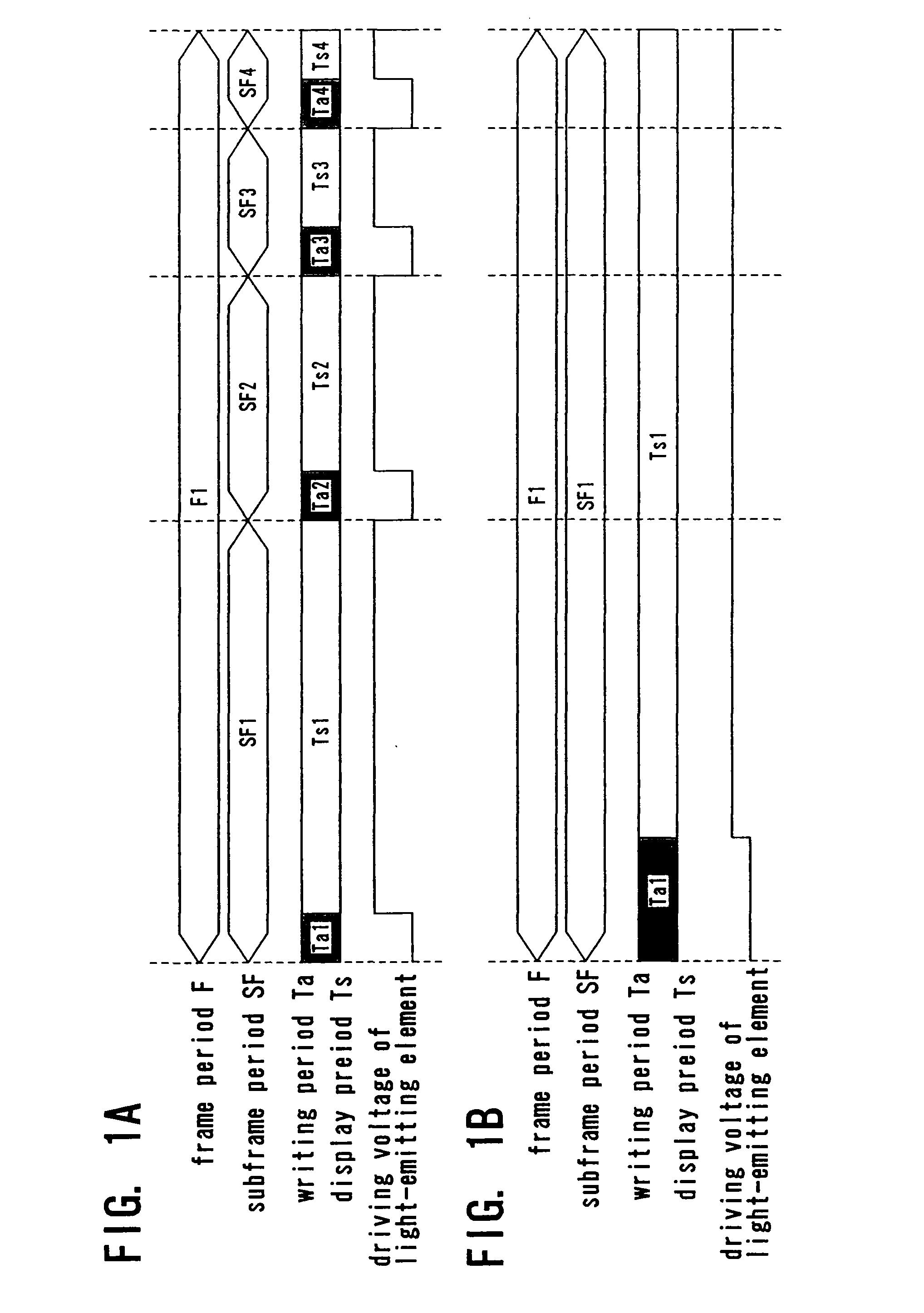
[0134] Embodiment Mode 1 of the invention is described. Here, similar to the conventional example, an example in which 4 bits are used in the first display mode is described.

[0135] Timing charts for a driving method of a display device of the invention are shown in FIGS. 1A and 1B. In general, in a display device into which an n-bit digital video signal (where n is a natural number) is inputted, it is possible to express 2n gray scales by using n subframe periods SF1 to SFn and an n-bit digital image signal in the first display mode, and it is possible to express 2 gray scales by using a 1-bit digital image signal in the second display mode by a switching operation. The display device of the invention can be applied to such a case.

[0136] Further in general, in a display device into which an n-bit digital video signal is inputted (where n is a natural number), it is possible to express n gray scales by inputting an n-bit digital image signal and using at least n subframe periods in...

embodiment mode 2

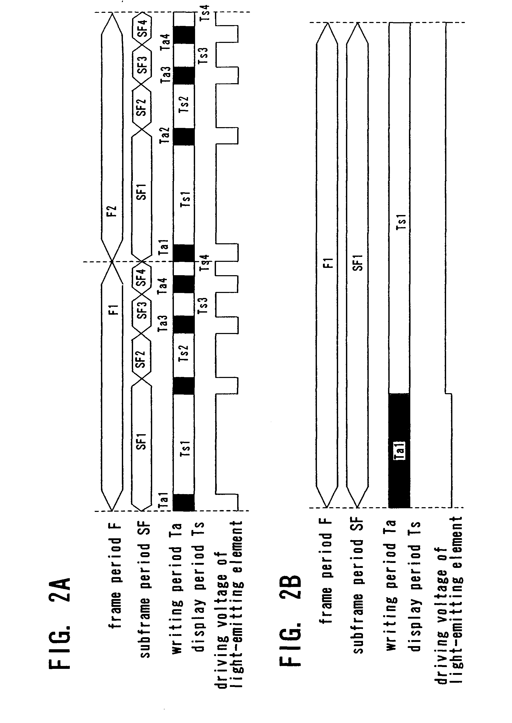
[0169] Embodiment Mode 2 of the invention is described. Here, similar to the conventional example, an example in which 4 bits are used in the first display mode is described.

[0170] Timing charts for a driving method of a display device of the invention are shown in FIGS. 9A and 9B. In general, considered is a display device into which an n-bit digital video signal (where n is a natural number) is inputted. It is possible to express 2n gray scales by using n subframe periods SF1 to SFn and an n-bit digital image signal in the first display mode. On the other hand, in the second display mode, 2m gray scales are expressed by using an m-bit digital image signal (where m is a natural number smaller than n) by a switching operation.

[0171] Further in general, in a display device into which an n-bit digital video signal is inputted (where n is a natural number), it is possible to express n gray scales by inputting an n-bit digital image signal and using at least n subframe periods in the ...

embodiment 1

[0187] Hereinafter, an embodiment mode of the invention is described.

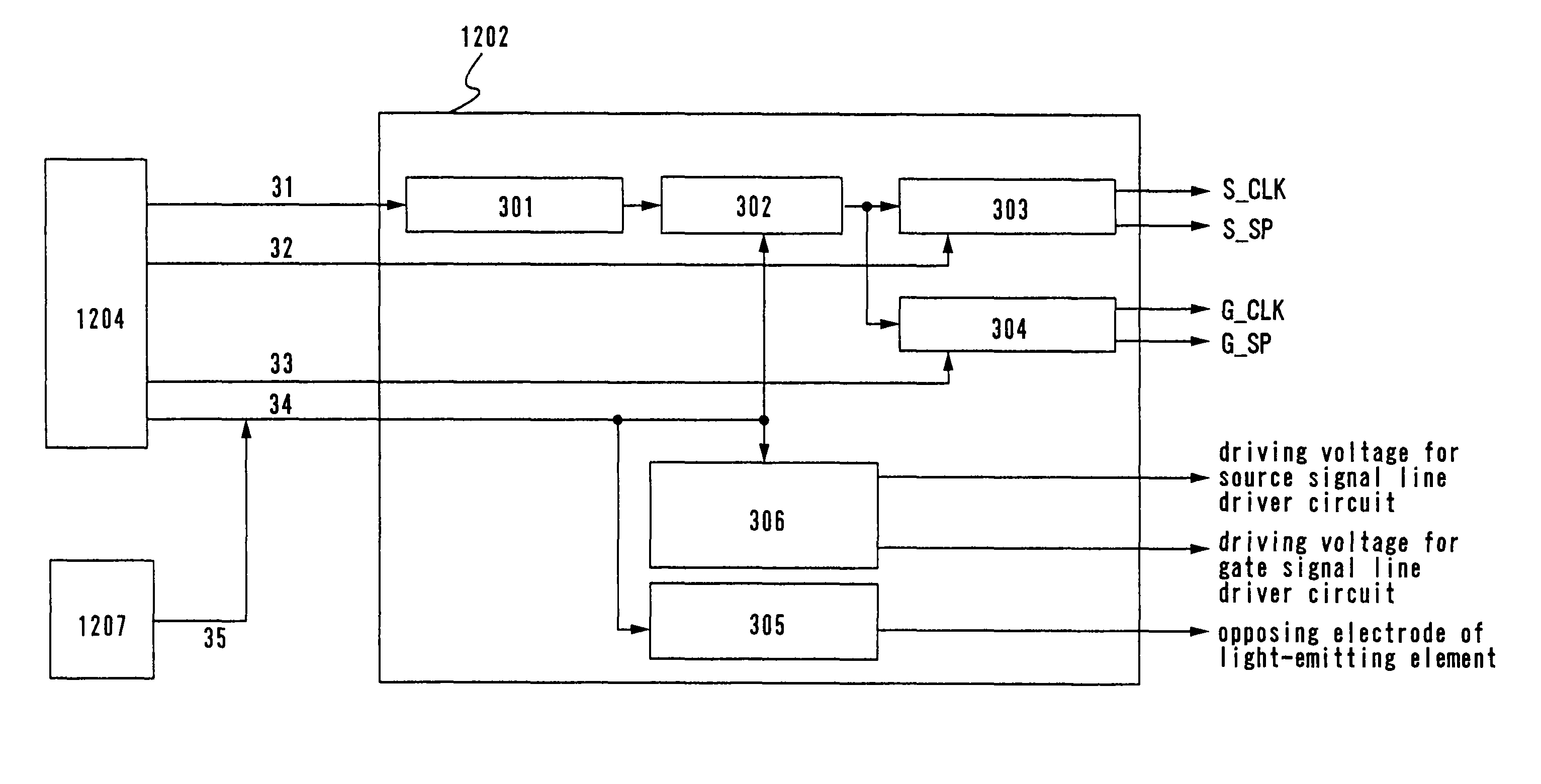
[0188] Description is made on a circuit for inputting a signal to perform a time gray scale driving method to a source signal line driver circuit and a gate signal line driver circuit with reference to FIG. 11.

[0189] In this specification, an image signal to be inputted to the display device is called a digital video signal. Note here that description is made on an example of a display device for displaying an image by being inputted a 4-bit digital video signal. Note that the invention is not limited to 4 bits.

[0190] A digital video signal is read into a signal controlling circuit 1201, and the signal controlling circuit 1201 outputs a digital image signal (VD) to a display 1200.

[0191] Note also that in this specification, a signal to be inputted into the display after being converted by the compilation of a digital video signal in the signal controlling circuit 1201 is called a digital video signal.

[0192] A ...


PUM


Abstract

Outside light is received using a light sensor, and in accordance with the outside light intensity, each of a first display mode which expresses multiple gray scales and a second display-y mode which expresses a gray scale smaller in number than that in the first display mode is switched and used. The switching is controlled by a display controller based on data of the outside light intensity. Accordingly, the visibility can be ensured in a wide range of situations, from under a fluorescent lamp in a dark place or inside, to under sunlight outside. In the second display mode, frequencies of a start pulse and a clock pulse to be inputted to a source signal line driver circuit are reduced and a driving voltage is decreased by the display controller; accordingly, a frame period can be longer than that in the first display mode and power consumption can be reduced.

Description

BACKGROUND OF THE INVENTION [0001] 1. Field of the Invention [0002] The present invention relates to a display device for performing display of an image by inputting a digital video signal. In particular, the present invention relates to a display device having light-emitting elements. Further, the present invention relates to an electronic apparatus using the display device. [0003] 2. Description of the Related Art [0004] A display device having a light-emitting element in each pixel and which performs display of an image by controlling light emission of the light-emitting elements is described below. [0005] The description in this specification is made using an element (OLED element) having a structure in which an organic compound layer which emits light when an electric field is generated is sandwiched between an anode and a cathode, as a light-emitting element; however, the invention is not limited to this. Any element which emits light by applying an electric field between the ...

Claims


Application Information

Patent Timeline
Patent Type & Authority Applications(United States)
IPC IPC(8): G09G3/30
CPCG09G3/20G09G3/2022G09G3/3225G09G2300/0861G09G2360/144G09G2310/0275G09G2330/021G09G2340/0428G09G2360/141G09G2310/0267
Inventor YAMAZAKI, SHUNPEIKOYAMA, JUNTANADA, YOSHIFUMIOSAME, MITSUAKIKIMURA, HAJIMEFUKUMOTO, RYOTAYANAI, HIROMISHISHIDO, HIDEAKI
Owner SEMICON ENERGY LAB CO LTD
Why Eureka
Try Eureka