Display device

a technology of display device and display device, which is applied in the direction of simultaneous indication of multiple variables, identification means, instruments, etc., can solve the problems of liquid crystal display disturbance and the invisibility of the display on the first display uni

Active Publication Date: 2017-03-16
YAZAKI CORP
View PDF1 Cites 19 Cited by
  • Summary
  • Abstract
  • Description
  • Claims
  • Application Information

AI Technical Summary

Benefits of technology

[0007]The present invention has been made in view of the above-mentioned circumstances, and an object of the invention is to provide a display device that can ensure proper visibility.

Problems solved by technology

Consequently, this may cause the visibility of the display on the first display unit and the liquid crystal display to be disturbed.

Method used


Image

  • Display device
  • Display device
  • Display device

Examples


first embodiment

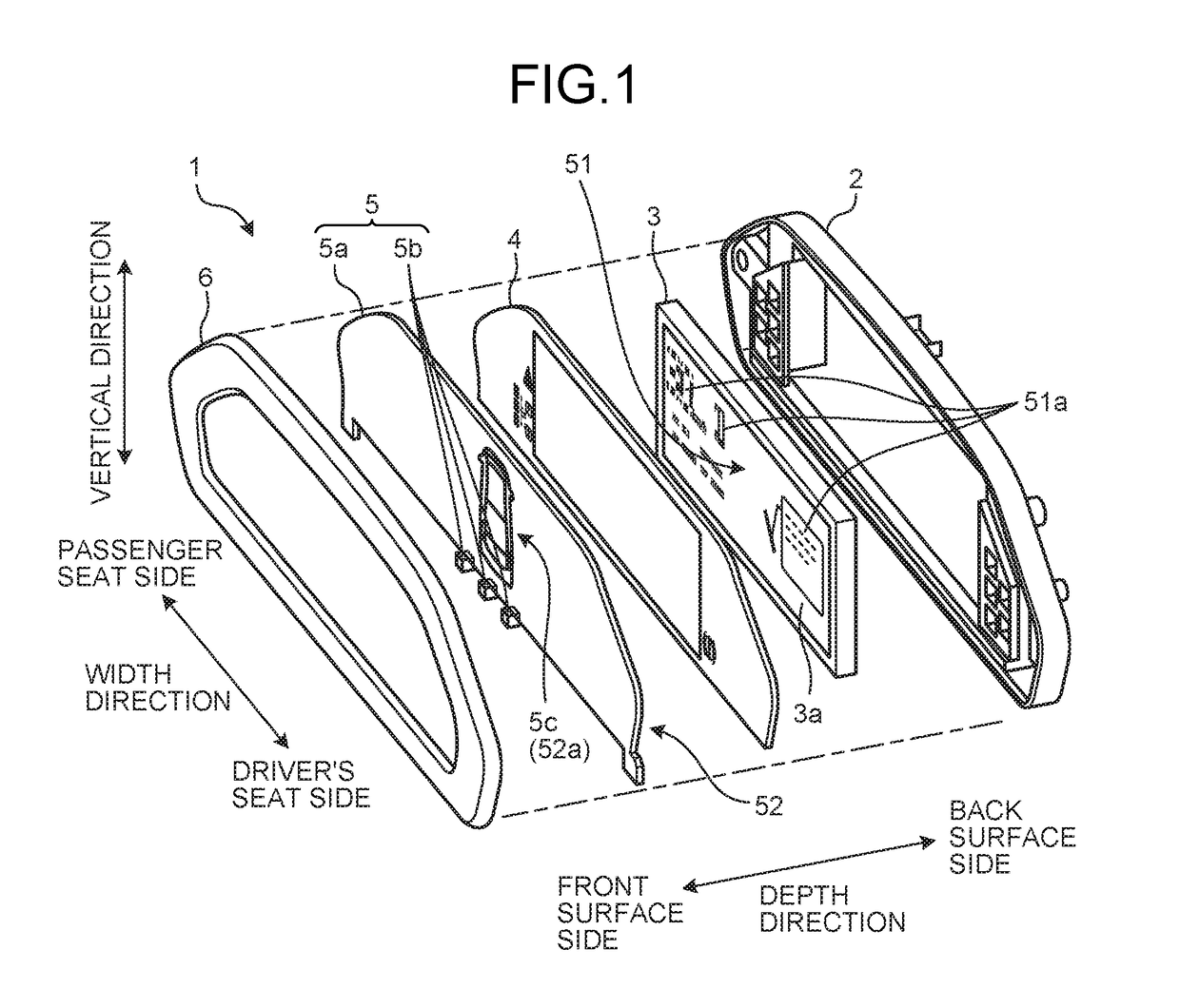
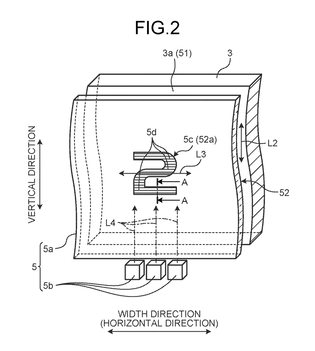
[0049]FIG. 1 is an exploded perspective view illustrating a schematic configuration of a display device according to a first embodiment. FIG. 2 is a schematic perspective view illustrating a schematic configuration of a superimposing display device of the display device in the first embodiment. FIG. 3 is a schematic cross-sectional view along the line A-A in FIG. 2. FIG. 4 is a partial cross-sectional view of the inside of an enclosing line B in FIG. 3. FIG. 5 is a schematic exploded perspective view illustrating a schematic configuration of a display of the display device in the first embodiment. FIG. 6 is a schematic front view of an image display surface and a transparent light guide plate when a polarization direction of the display and an extending direction of grooves are orthogonal to each other. FIG. 7 is a schematic diagram for explaining the operation when the polarization direction of the display and the extending direction of the grooves are orthogonal to each other. FIG...

example

[0091]FIGS. 13, 14, 15, 16, 17, and 18 are schematic diagrams for explaining prerequisites of a luminance measurement test of a display device in an example. FIG. 19 is a chart representing the result of the luminance measurement test of the display device in the example. The following describes the example of the display device with reference to FIGS. 13 to 19.

[0092]The display device 1 in the foregoing first embodiment was prototyped, and a luminance measurement test that measures, with a luminance measurement camera, the luminance of the area of the pattern 5c (the real image pattern 52a) in the transparent light guide plate 5a and of the area in the periphery of the pattern 5c in the transparent light guide plate 5a was conducted by using the display device 1. In the display device 1 of this example, the display 3, the transparent light guide plate 5a, and others were arranged so as to be arranged as illustrated in FIG. 13. That is, in the display device 1 of this example, the t...

second embodiment

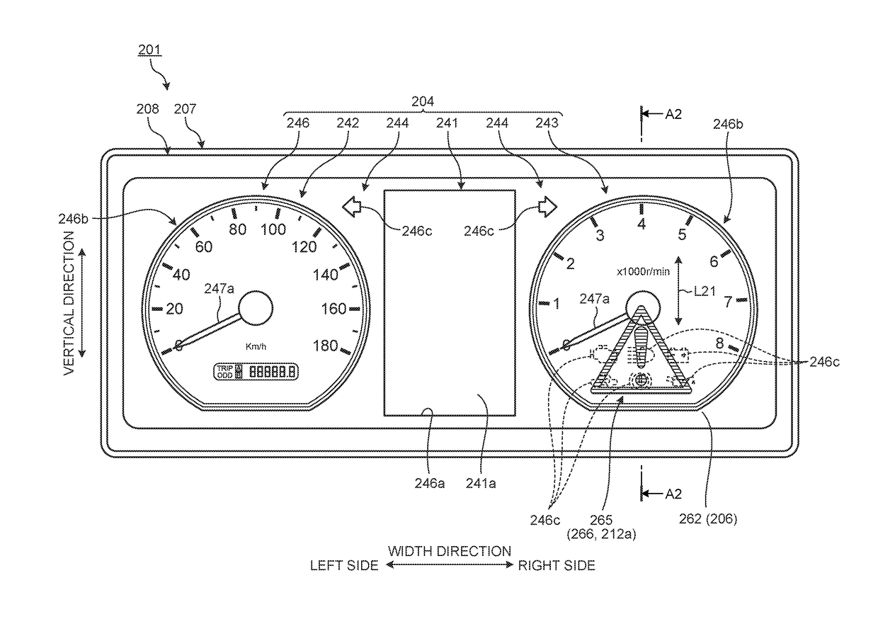
[0096]FIG. 20 is a front view of the front surface side in a depth direction of a display device according to a second embodiment. FIG. 21 is a cross-sectional view along the line A2-A2 indicated in FIG. 20. FIG. 22 is a schematic perspective view illustrating a schematic configuration of a front-face side display device of the display device in the second embodiment. FIG. 23 is a schematic diagram for explaining one example of a display form in the display device in the second embodiment. FIG. 24 is a schematic exploded perspective view of the display device in the second embodiment. The display device in the second embodiment differs in the configuration of a first display surface from that of the first embodiment. In addition, as for the configurations, operations, and effects that are common to those of the above-described first embodiment, the redundant descriptions are omitted as much as possible.

[0097]In a display device 201 in the second embodiment illustrated in FIGS. 20, 2...


PUM


Abstract

A display device includes an image display device that includes an image display surface that emits light polarized in one direction and displays an image; and a superimposing display device that includes a transparent light guide plate that is provided overlapping the image display surface, transmits the light emitted from the image display device, and also has grooves constituting a pattern formed thereon, includes a light source that irradiates an end surface of the transparent light guide plate with light, and is switched between display and non-display of the pattern based on lighting and non-lighting of the light source. A polarization direction of the image display device and an extending direction of the grooves intersect at an angle range of 75° to 105°. Accordingly, the display device can ensure proper visibility.

Description

CROSS-REFERENCE TO RELATED APPLICATION[0001]This application is a continuation application of International Application PCT / JP2015 / 065268, filed on May 27, 2015, and designating the U.S., the entire contents of which are incorporated herein by reference.BACKGROUND OF THE INVENTION[0002]1. Field of the Invention[0003]The present invention relates to a display device.[0004]2. Description of the Related Art[0005]As a conventional display device that is fitted to a vehicle and the like, Japanese Patent Application Laid-open No. 2012-032286, for example, discloses a display device that includes a first display unit that displays instruments of the vehicle and a second display unit that displays additional information. The second display unit of the display device is arranged with a plurality of colorless transparent light guide plates in an overlapping manner on the face of a dial of the first display unit, and on the light guide plates, patterns are formed with grooves. In such a displa...

Claims


Application Information

Patent Timeline
Patent Type & Authority Applications(United States)
IPC IPC(8): B60K35/00G09F13/00G09F9/00
CPCB60K35/00G09F9/00G09F13/00B60K2350/206B60K2350/2086B60K2350/2039B60K2350/2056B60K37/06G01D7/06B60K2370/1438B60K2370/46B60K2370/81B60K2370/828B60K2370/834B60K2370/20B60K2370/34B60K2370/347B60K2370/693
Inventor FUJITA, SUNAO
Owner YAZAKI CORP
Why Eureka
Try Eureka