Music data display control apparatus and method

a control apparatus and music data technology, applied in the field of music data display control apparatus and method, can solve the problems of difficult for users to clearly view the voice code, difficulty in ensuring the visibility of information associated, and difficulty in a user's viewing of voice cod

Active Publication Date: 2013-05-09
YAMAHA CORP
View PDF6 Cites 19 Cited by
  • Summary
  • Abstract
  • Description
  • Claims
  • Application Information

AI Technical Summary

Benefits of technology

[0004]In view of the foregoing, it is an object of the invention is to provide a music data display control apparatus capable of ensuring visibility of information associated with each note and displaying the information, even when a music score display area is reduced and displayed.

Problems solved by technology

Therefore, there is a possibility that the voice code with a predetermined display size is not fit into the inside of the voice image.
In this case, however, there is a problem in that it is difficult for a user to view the voice code clearly.
However, the same problem may also occur when various kinds of information (for example, a character string or a sign indicating a musical expression such as vibrato) associated with each note is written together and displayed in the note image.

Method used


Image

  • Music data display control apparatus and method
  • Music data display control apparatus and method
  • Music data display control apparatus and method

Examples


first embodiment

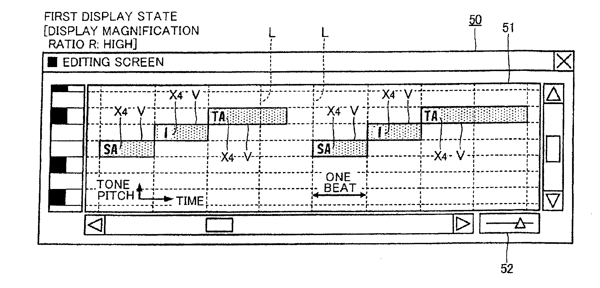
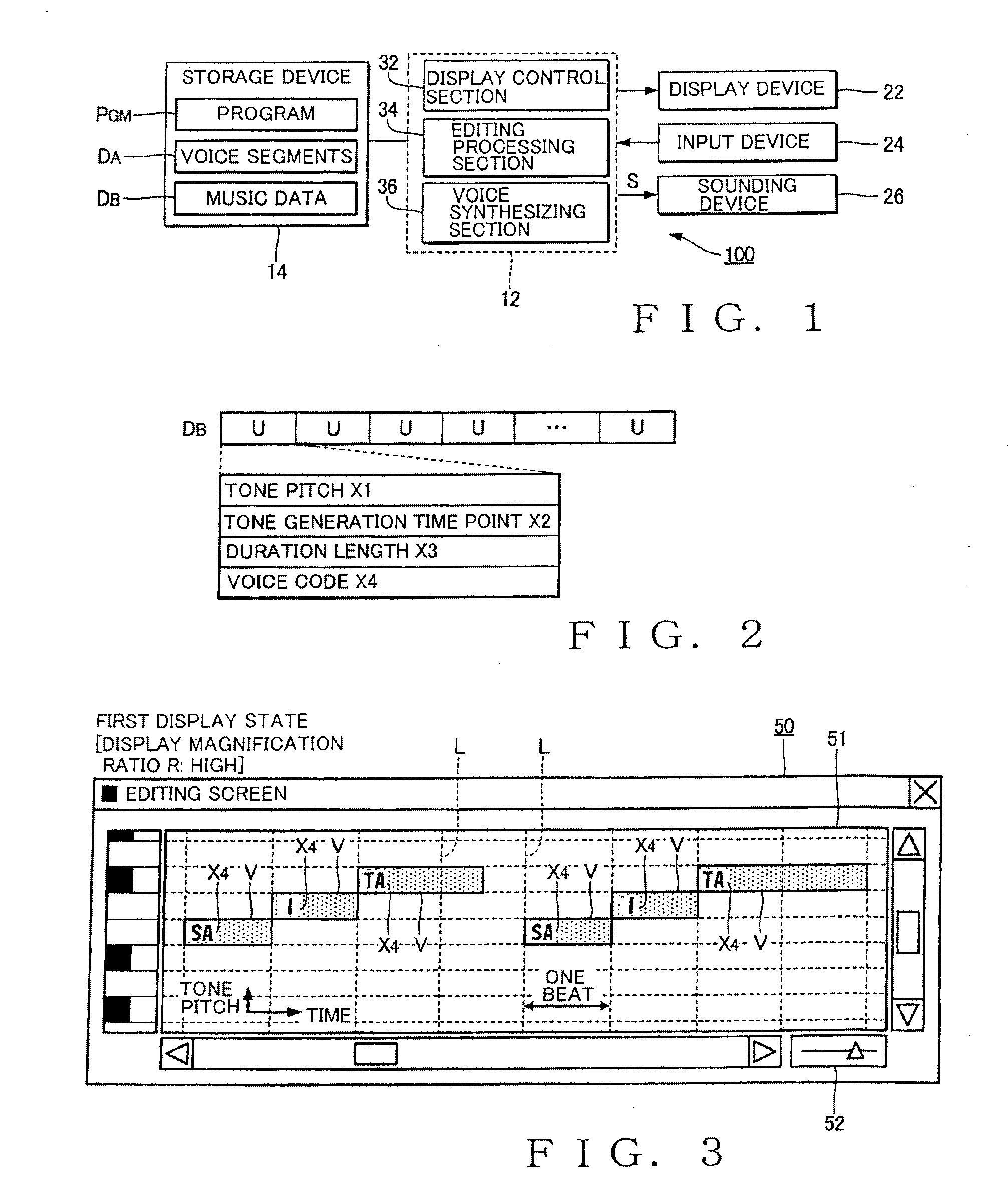
[0029]FIG. 1 is a block diagram illustrating a voice synthesizing apparatus 100 employing an embodiment of a music data display control apparatus of the present invention. The voice synthesizing apparatus 100 is a signal processing apparatus that generates a voice signal S of a singing voice through segment connection type voice synthesis. As illustrated in FIG. 1, the voice synthesizing apparatus 100 may be realized by a computer system that includes an arithmetic processing device 12, a storage device 14, a display device 22, an input device 24, and a sounding device 26. For example, the voice synthesizing apparatus 100 may be realized by a stationary information processing apparatus (personal computer) or a portable information processing apparatus (a portable telephone or a portable information terminal).

[0030]The arithmetic processing device 12 realizes a plurality of functions (i.e., functions as a display control section 32, an editing processing section 34, and a voice synth...

second embodiment

[0048]A second embodiment of the present invention will be described. The above-described reference numerals are given to the same constituent elements as those of the first embodiment in the operations and functions in each embodiment to be exemplified, and the detailed description thereof will be appropriately omitted.

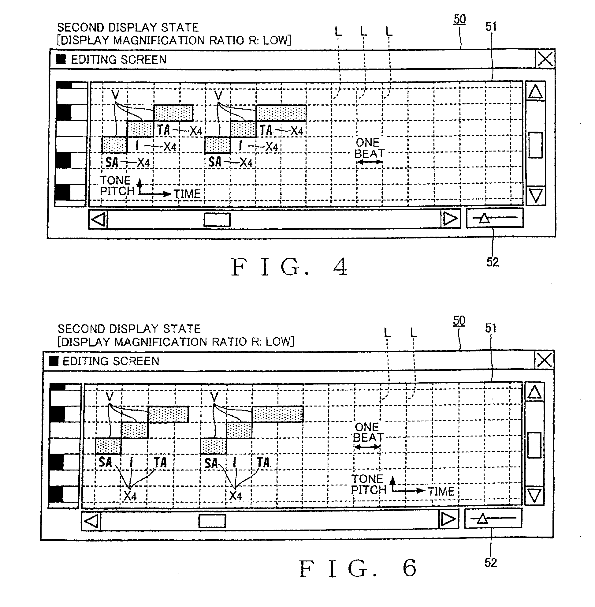
[0049]FIG. 6 is a schematic view illustrating an editing screen 50 in the second display state according the second embodiment. In the first embodiment, the positions of the voice codes X4 in the tone pitch axis direction are configured to differ from each other for each note in the second display state. In the second embodiment, as illustrated in FIG. 6, the plurality of voice codes X4 in the music score display area 51 is arranged in a line in the time axis direction. Specifically, the display control section 32 arranges the plurality of voice codes X4 in the music score display area 51 in a straight line at positions located below by suitable distances from the bo...

third embodiment

[0051]FIG. 7 is a schematic view illustrating an editing screen 50 according to a third embodiment. In FIG. 7, a display example of the editing screen 50 is illustrated where the display magnification ratio R is further decreased from the second display state exemplified in FIG. 6. The display image in the first display state is the same as that of the first embodiment.

[0052]When the display magnification ratio R falls below a predetermined threshold value in the second display state, the display control section 32 divides a time series of a plurality of voice codes X4 corresponding to the notes in the music score display area 51 into the front and rear portions on the time axis, and arranges only the front portion in the music score display area 51 (outside each note image V), as illustrated in FIG. 7. That is, the rear portion is not displayed. In FIG. 7, a case is exemplified where the time series of the voice codes X4, “sa-i-ta, sa-i-ta,” in the display target portion is divided...


PUM


Abstract

A display area, in which a note is displayed on two-axis coordinates configured by a tone pitch axis and a time axis, is displayed on a display device. A display magnification ratio used in the display area is variable. A note image of a given note is displayed in the display area to be arranged in correspondence with a tone pitch and a tone generation time of the note. The size of the note image is varied with the display magnification ratio. Relevant information is displayed in association with the note image displayed in the display area in such a manner that the relevant information is arranged inside the note image of the note in a first display state and the relevant information is arranged outside the note image of the note in a second display state with a display magnification ratio lower than that of the first display state.

Description

BACKGROUND[0001]The present invention relates to a technique for displaying music data.[0002]Techniques for displaying a time series of a plurality of notes designated by music data on a display device have conventionally been suggested as schemes for displaying music score without use of a staff notation. For example, Japanese Patent Application Laid-open Publication No. 2011-128186 discloses a technique for displaying an image (hereinafter, referred to as a “note image”) that expresses each note of a music piece in a piano-roll type music score display area indicated by two-axis coordinates configured by a combination of a tone pitch axis and a time axis, and for arranging and displaying a voice code (for example, one or more letters of lyrics corresponding to each note of a singing music piece) granted to each note, for example, in an inside of a rectangular note image.[0003]However, when a display magnification ratio used in the music score display area decreases (for example, w...

Claims


Application Information

Patent Timeline
Patent Type & Authority Applications(United States)
IPC IPC(8): G10G1/00
CPCG10H1/0008G10H2220/126G10H2220/011
Inventor IRIYAMA, TATSUYA
Owner YAMAHA CORP
Why Eureka
Try Eureka