Clothes hanger roller blocking and releasing device of clothes manufacturing system
A technology of hangers and rollers is applied in the field of blocking and releasing devices for hangers and rollers, which can solve the problems of unstable coordination, inability to block and release by hangers, and achieve the effects of stable blocking and releasing, and stable coordination.
- Summary
- Abstract
- Description
- Claims
- Application Information
AI Technical Summary
Problems solved by technology
Method used
Image

Examples
Embodiment 1
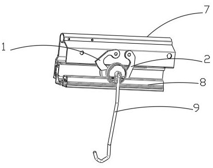
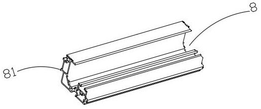
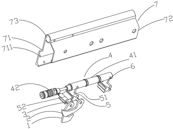
[0033] Such as figure 1 , 2 As shown in and 3, the clothing system includes a guide rail 8, and a clothes hanger 9 straddles the guide rail 8 to roll, and one side of the guide rail 8 is integrally formed with two connecting pieces 81 arranged in an "eight" shape. Two protruding clamping strips 711 are integrally formed on the inner wall surface of the lower end side of the side wall 71 of the blocking release device. The two clamping strips 711 extend along the length direction of the base frame 7, and a bayonet is formed between the two clamping strips 711. , for inserting two connecting pieces 81 on the guide rail 8, and realize the connection and fixation between the guide rail 8 and the base frame 7 by pressing the connecting pieces by the screws threadedly coupled to the clamping strips. The other side wall 72 is used for inserting into the groove provided on the outer peripheral surface of the roller of the clothes hanger 9 on the guide rail 8 , so that the roller of t...
Embodiment 2
[0040] Such as Figure 6 and Figure 7 As shown, this embodiment is basically the same as Embodiment 1, the difference is that the rollers of the clothes hanger 9 are double rollers, and the pivot 3 coupled with the blocking arm 2 is inserted into the driving gear 51 which is relatively downstream.
[0041] The working process of the second embodiment of the present invention is as follows:
[0042] Such as Figure 8 , 9 , 10, 11, 12 and 13, the front roller of the clothes hanger 9 enters the blocking release device, and then the blocking release device releases the rear roller of the adjacent clothes hanger 9 on the downstream side of the clothes hanger 9, and then the rear roller of the clothes hanger 9 enters the blocking Release device, then block the front roller of the release device to release the clothes hanger 9, and then the front roller of the adjacent clothes hanger 9 on the upstream side of the clothes hanger 9 enters the blocking release device, and finally bl...
PUM
 Abstract
Description
Claims
Application Information
 - R&D
- Intellectual Property
- Life Sciences
- Materials
- Tech Scout
- Unparalleled Data Quality
- Higher Quality Content
- 60% Fewer Hallucinations
Browse by: Latest US Patents, China's latest patents, Technical Efficacy Thesaurus, Application Domain, Technology Topic, Popular Technical Reports.
© 2025 PatSnap. All rights reserved.Legal|Privacy policy|Modern Slavery Act Transparency Statement|Sitemap|About US| Contact US: help@patsnap.com