

Simulation test equipment and method for super-load anchor pile cross beam counter-force device
A technology of reaction force device and simulation test, which is applied in the test of basic structure, construction, and basic structure engineering, etc., can solve the problems of inoperability and uneconomical
Pending Publication Date: 2021-05-28
SHANGHAI TONGJI CONSTR QUALITY INSPECTION STATION
View PDF0 Cites 0 Cited by
- Summary
- Abstract
- Description
- Claims
- Application Information
AI Technical Summary
Problems solved by technology
But these two methods are nei
Method used
View moreImage
Smart ImageViewing Examples

Examples
 PUM
| Property | Measurement | Unit |
|---|---|---|
| Diameter | aaaaa | aaaaa |
Abstract
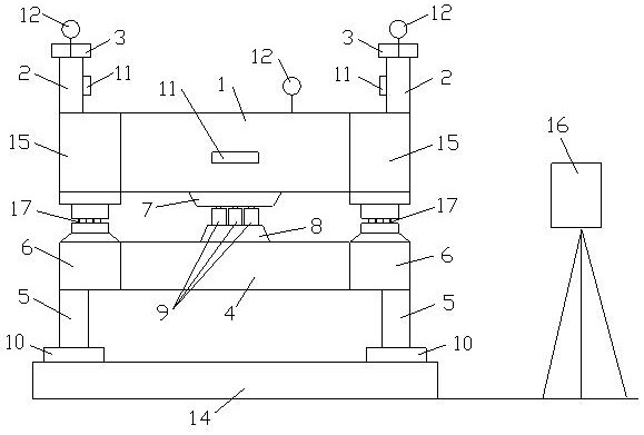
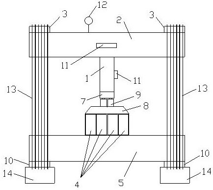
The invention discloses simulation test equipment and method for a super-load anchor pile cross beam counter-force device. In the equipment, the middle parts of two secondary beams are arranged on the top faces of the two ends of a main beam, and anchor pile caps are arranged on the top faces of the two ends of the secondary beams; two secondary pressure-bearing counter-force box girders are arranged on a test platform, and counter-force anchor pile caps are arranged on the bottom faces of the two ends of the secondary pressure-bearing counter-force box girders; four main pressure-bearing counter-force box girders are arranged side by side, and the two ends of the four main pressure-bearing counter-force box girders are arranged on the top faces of the middles of the two secondary pressure-bearing counter-force box girders; four-hole box girders are arranged at the two ends of the four main pressure-bearing counter-force box girders in a sleeving mode; an upper steel box cushion and a lower steel box cushion are arranged on the bottom face of the middle of the main beam and the top faces of the middles of the four main pressure-bearing counter-force box beams; six sets of jacks are arranged between the upper steel box cushion and the lower steel box cushion; a plurality of first twisted steel bars are welded between the anchor pile caps and the counter-force anchor pile caps; and a displacement sensor and a dial indicator are arranged on the main beam and the two secondary beams and used for detecting rigidity and deformation. According to the method, the main beam and the four main pressure-bearing counter-force box beams are subjected to graded loading and unloading through six sets of jacks, and whether the main beam and the secondary beams meet the requirement of the maximum load or not is judged.
Description
technical field [0001] The invention relates to the technical field of construction engineering, in particular to a simulation test equipment and method for super-large-load anchor pile beam reaction devices. Background technique [0002] The static load test of pile foundation is the most primitive and basic method to determine the bearing capacity of single pile, and it is also the most reliable method. The single pile static load test is a test method close to the actual working conditions of vertical compression. The load acts on the top of the pile to cause displacement (settlement) of the top of the pile, and the load-settlement (P-S) curve of a single test pile can be obtained. Sedimentation-time logarithmic (S-lgt) curves can be obtained, as well as other curves required for analysis. [0003] Generally, single pile static load test equipment is composed of loading device and load and deformation observation device. The loading device is composed of main beam, seco...
Claims
Login to View More Application Information
Patent Timeline
 IPC IPC(8): E02D33/00
CPCE02D33/00
Inventor孙启栋张西峰孙延生刘云朋郝世龙孙鑫钱锟余士伟董建纲
OwnerSHANGHAI TONGJI CONSTR QUALITY INSPECTION STATION