A Constant Linear Load Simulator

A load simulation and linear technology, applied in the field of steering gear, to achieve high reliability, meet the accuracy and stability test, and the effect of stable linear force output

Active Publication Date: 2019-08-13
BEIJING AUTOMATION CONTROL EQUIP INST
View PDF4 Cites 0 Cited by
  • Summary
  • Abstract
  • Description
  • Claims
  • Application Information

AI Technical Summary

Problems solved by technology

At present, there is no linear force loading device that can be used to simulate the accuracy and stability of the action of the steering gear.

Method used


Image

  • A Constant Linear Load Simulator
  • A Constant Linear Load Simulator
  • A Constant Linear Load Simulator

Examples


Embodiment 1

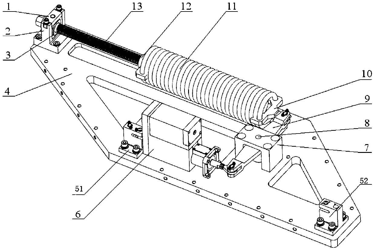
[0023] Such as figure 1 As shown, the constant linear load simulation device of the present invention has a bottom plate 4, which is flat and hollowed out for weight reduction. A screw rotation base 2 is fixedly installed on the bottom plate 4 .

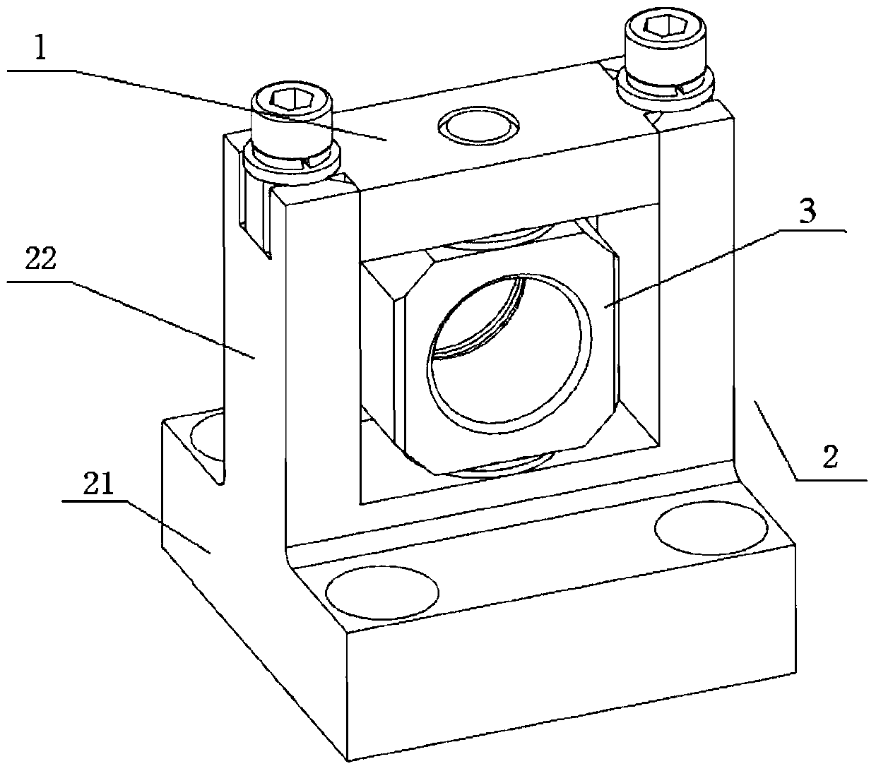
[0024] Screw swivel base 2 such as figure 2 As shown, it has a base 21 and an upper frame 22 . The base 21 is fixedly mounted on the bottom plate 4 by screws, and the upper frame 22 is fixedly connected with the base 21 . The upper frame 22 is in the shape of a rectangular frame without an upper frame, and pin holes are provided on the lower frame of the upper frame 22 . The cover plate 1 is installed on the top of the upper frame 22 by screws, the cover plate 1 and the upper frame 22 together form a complete rectangular frame, the cover plate 1 is also provided with pin holes, and the pin holes on the cover plate 1 are connected with the The pin holes on the lower frame of the upper frame 22 are coaxial.

[0025] The screw rot...

Embodiment 2

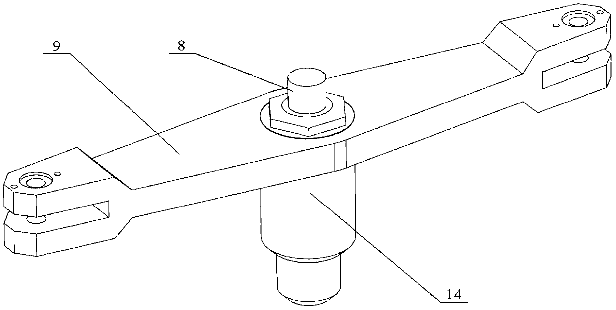
[0032] Such as figure 1 As shown, the difference between this embodiment and Embodiment 1 is that a second positioning block 52 is also provided on the bottom plate 4 , which is also used for fixing and installing the steering gear 6 . The rear hinge ear of the steering gear 6 can be hinged with the first positioning block 51, and the front hinge hinge is hinged at the end of an arm of the steering rod 9. Under the natural state of the spring 11, the shaft of the output shaft of the steering gear 6 Vertical to the straight line formed by the two arms of steering rod 9. The setting position of the second positioning block 52 is such that the spring 11 can provide pressure load for the steering gear 6 when stretched.

[0033] When the device of the present invention is in use, the nut 12 is rotated so that the nut 12 moves in the direction above the bottom plate 4 along the axial direction of the screw rod 13, and the movement of the nut 12 makes the spring 11 stretch, and afte...


PUM


Abstract

The invention belongs to the technical field of steering engines, and particularly relates to a constant linear load simulation device. The linear load simulation device comprises a cover plate, a screw rod rotating base, a screw rod rotating pin, a baseplate, a first locating block, a limiting block, a steering rod locating pin, a steering rod, a spring fixator, a spring, a nut, a screw rod and a tacking nut. The problem in the prior art that there is no linear force loading equipment which can be used for testing the accuracy and the degree of stability of the steering engine action in a simulation way can be solved. The characteristics that the elongation of the spiral spring is in direct proportion to the size of the tensile force, and the linear force output is stable and high in reliability are utilized, the elongation of the spring is fixed through thread self-locking, and direction change of the linear force can be guaranteed through combination of multiple single-degree-of-freedom joints so as to have force output of forward and backward directions, the linear simulation load of forward and backward directions can be provided for the linear steering engine, and testing of the accuracy and the degree of stability of the steering engine action can be met.

Description

technical field [0001] The invention belongs to the technical field of steering gear, and in particular relates to a constant linear load simulation device. Background technique [0002] With the continuous development of aircraft systems towards supersonic speed, long range and high precision, the linear electric steering gear requires greater output force, faster movement speed, more accurate positioning accuracy, and smaller space layout. Due to the limitations of factors such as insufficient space in the environmental test chamber, the loading device of the steering gear needs to provide accurate and stable linear loads in a small space when the steering gear moves quickly. At present, there is no linear force loading device that can be used to simulate the accuracy and stability of the action of the steering gear. Contents of the invention [0003] The technical problem to be solved by the present invention is: there is no linear force loading device that can be used...

Claims


Application Information

Patent Timeline
Patent Type & Authority Patents(China)
IPC IPC(8): G09B25/00
CPCG09B25/00
Inventor 王永乐段小帅
Owner BEIJING AUTOMATION CONTROL EQUIP INST
Why Eureka
Try Eureka