Camshaft testing equipment

A test equipment and camshaft technology, applied in the mechanical field, can solve the problems of unable to test the cam, unable to accurately measure the pre-pressure, unable to adapt to the replacement of the camshaft test piece, etc., to achieve the effect of saving test costs and reasonable structural design

Pending Publication Date: 2019-10-18
SUZHOU NUCLEAR POWER RES INST +2
View PDF1 Cites 0 Cited by
  • Summary
  • Abstract
  • Description
  • Claims
  • Application Information

AI Technical Summary

Problems solved by technology

[0004] In the prior art, such as Chinese patent application number: 201620850696.1, patent name: an invention patent for a diesel engine camshaft and tappet wear test device, the technical solution has the following disadvantages: 1. The mechanical structure is a closed structure , unable to adapt to the replacement of various camshaft test pieces, it is necessa

Method used


Image

  • Camshaft testing equipment
  • Camshaft testing equipment
  • Camshaft testing equipment

Examples


Embodiment Construction

[0028]In order to enable those skilled in the art to better understand the technical solutions of the present invention, the technical solutions in the embodiments of the present invention will be clearly and completely described below in conjunction with the drawings in the embodiments of the present invention. Obviously, the described implementation Examples are only some of the embodiments of the present invention, not all of them. Based on the embodiments of the present invention, all other embodiments obtained by persons of ordinary skill in the art without making creative efforts shall fall within the protection scope of the present invention.

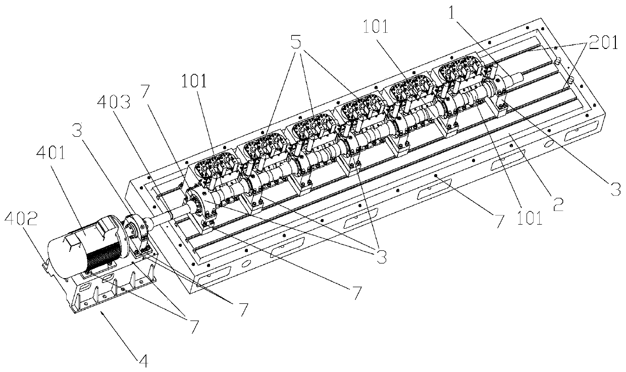
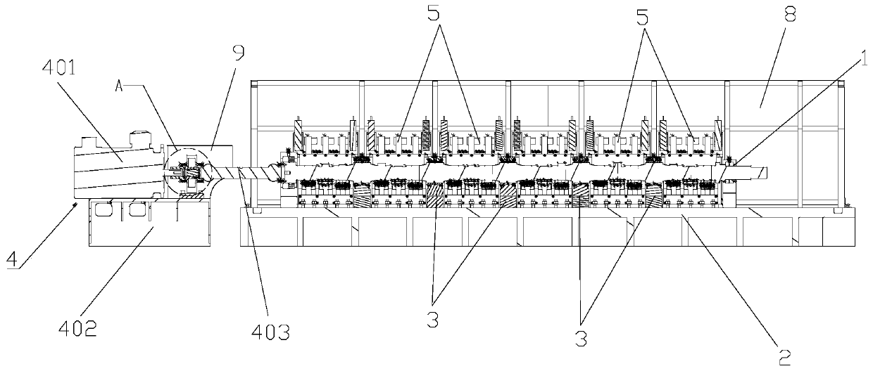
[0029] refer to Figure 1-8 As shown, the camshaft 1 testing equipment of this embodiment includes a base 2, a loading device 5 arranged on the base 2, a supporting device for supporting the camshaft 1, and a driving device 4 for driving the camshaft 1 to rotate. A protective cover 8 is also provided on the base 2 to cover the c...


PUM


Abstract

The invention discloses camshaft testing equipment. The camshaft testing equipment comprises a base, loading devices arranged on the base, a supporting device for supporting a camshaft and a driving device for driving the camshaft to rotate; each loading device comprises a support, loading swing arm assemblies matched with cams arranged on the camshaft and preloading assemblies mutually cooperating with the loading swing arm assemblies; each loading swing arm assembly comprises a swing arm and a reading board perpendicularly arranged in the middle of the swing arm, rollers are arranged at thetwo ends of each swing arm, standing boards are arranged on the supports, and the middles of the swing arms are rotatably connected to the standing boards; and each preloading assembly comprises a shell, a gland located over the shell, an elastic part, an upper spring base and a lower spring base, wherein the elastic part and the upper spring base are located in the space formed between the shelland the gland,the upper end of the elastic part acts on the upper spring base, and the lower end of the elastic part acts on the lower spring base.

Description

technical field [0001] The invention belongs to the technical field of machinery, and in particular relates to a camshaft testing device. Background technique [0002] The camshaft is the core part of the diesel generator for nuclear power emergency. Through the rotation of the cams with different phase angles, the opening and closing of the crankshaft valve is controlled to provide the fresh air necessary for combustion of the diesel generator. The camshaft is inside the diesel generator High-speed rotation, the maximum rotation speed is 750rpm. At this speed, because the cam is impacted by the cyclic force from the valve spring and the combustion cylinder, the cam surface of the camshaft is prone to contact fatigue wear, and high temperature is likely to occur between the journal of the camshaft and the bearing bush, reducing the camshaft The operating life of the diesel generator will affect the overall stability and reliability of the diesel generator. [0003] At pres...

Claims


Application Information

Patent Timeline
IPC IPC(8): G01M13/00
CPCG01M13/00
Inventor 覃恩伟王博尹嵩魏少翀陆海峰潘晨阳史一岭吴树辉
Owner SUZHOU NUCLEAR POWER RES INST
Why Eureka
Try Eureka