a fan

A technology of fans and connecting parts, which is applied in the direction of mechanical equipment, machines/engines, liquid fuel engines, etc., can solve the problems of cumbersome installation process and inconvenient operation, and achieve the effect of convenient operation and installation

Active Publication Date: 2022-07-08
山东亚通科技集团有限公司
View PDF8 Cites 1 Cited by
  • Summary
  • Abstract
  • Description
  • Claims
  • Application Information

AI Technical Summary

Problems solved by technology

However, the existing axial flow fans still have deficiencies in use. The shape of the axial flow fans is relatively simple. The axial flow fan is fixed, the installation process is cumbersome, and it is not easy to operate

Method used


Image

  • a fan
  • a fan
  • a fan

Examples


Embodiment 1

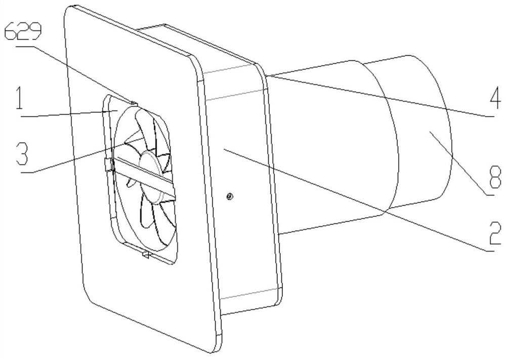
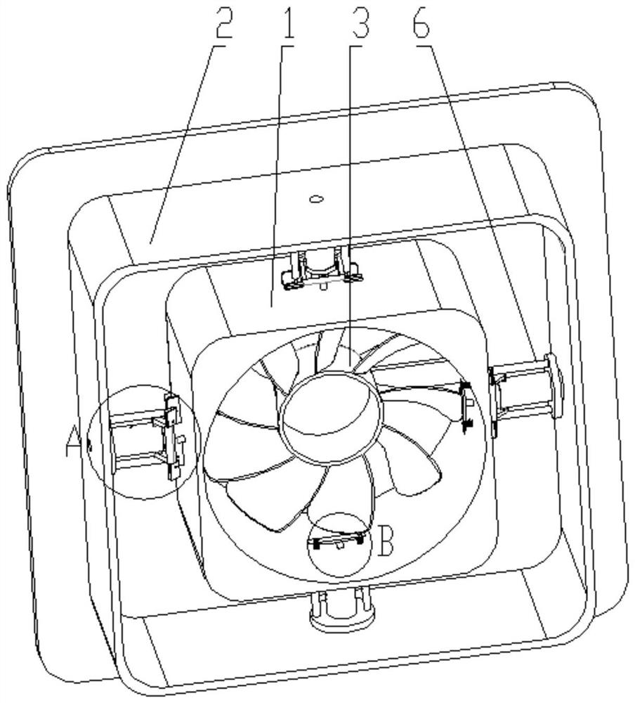
[0043] see Figure 1-Figure 9 , a fan, comprising a fan casing and a fan body 3 arranged inside the fan casing, the fan casing includes an inner frame body 1 and an outer frame body 2, and the fan body 3 is arranged on the inner frame body 1;

[0044] The outer frame body 2 is provided with a number of installation assemblies 6; the installation assemblies 6 are preferably arranged symmetrically, and can be installed at the four corners of the outer frame body 2 or at the middle position of each side, and the specific number can be based on the actual number. Depends.

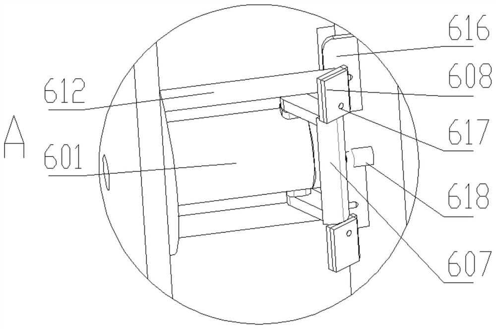
[0045]The installation assembly 6 includes a cylinder body 601, a combustion chamber 603 is arranged in the cylinder body 601, a combustible material 604 that burns to generate a large amount of gas is arranged in the combustion chamber 603, and a cylindrical connector is arranged at one end of the cylinder body 601 close to the outer frame body 2 One 602, a sealed space is formed between the cylindrical conne...

Embodiment 2

[0054] see Figure 10-Figure 14 , a fan, comprising a fan casing and a fan body 3 arranged inside the fan casing, the fan casing includes an inner frame body 1 and an outer frame body 2, and the fan body 3 is arranged on the inner frame body 1;

[0055] The outer frame body 2 is provided with a number of mounting components 6; the mounting components 6 are preferably arranged symmetrically, and can be installed at the four corners of the outer frame body 2, and the specific number can be determined according to the actual situation.

[0056] The installation assembly 6 includes a cylinder body 601, a combustion chamber 603 is arranged in the cylinder body 601, a combustible material 604 that burns to generate a large amount of gas is arranged in the combustion chamber 603, and a cylindrical connector is arranged at one end of the cylinder body 601 close to the outer frame body 2 One 602, a sealed space is formed between the cylindrical connecting piece 602 and the combustion c...

Embodiment 3

[0066] see Figure 7 and Figure 8 , On the basis of Embodiment 1 or Embodiment 2, it also includes a protective plate 4 arranged at one end of the outer frame body 2 , and an air duct communicated with the inner rectangle 1 is arranged on the protective plate 4 .

[0067] An external air duct 8 is inserted into the air duct 5, and a protective net is arranged at the outer end of the external air duct 8, and the protective net is arranged outside the wall.

[0068] The inner end of the external air duct 8 is provided with an annular groove, the annular groove is provided with an annular air bag 7, the inner wall of the air duct 5 is axially distributed with a number of annular limit grooves 401 that cooperate with the annular air bag 7, and the external air duct 8 The inflated annular air bag 7 is pushed into the annular limiting groove 401, and the annular air bag 7 is provided with an air valve.


PUM


Abstract

The invention provides a fan, which belongs to the technical field of fan equipment. Its technical scheme is: a fan, comprising a fan casing and a fan body arranged inside the fan casing, characterized in that the fan casing includes an inner frame body and an outer frame body, and the fan The main body is arranged on the inner frame body; the outer frame body is arranged with several installation components; the installation components include a cylinder body, a combustion chamber is arranged in the cylinder body, and a combustion chamber is arranged in the combustion chamber to generate a large amount of gas The combustible material, one end of the cylinder close to the outer frame is provided with a cylindrical connecting piece, a sealed space is formed between the cylindrical connecting piece and the combustion chamber, the combustible material burns, the Under the action of gas, the column-shaped connecting piece can penetrate into the wall through the outer frame. The beneficial effects of the present invention are: the fan is easy to install and can avoid using a drill bit to make holes on the surface of the wall.

Description

technical field [0001] The invention relates to the technical field of fan equipment, in particular to a fan. Background technique [0002] The motor and blades of the axial flow fan are all in the shell, which is used for local ventilation. The ventilation effect is obvious and safe. It can be used in metallurgy, chemical light industry, food factories, office buildings, residences and other places that need ventilation. , stable and reliable, features a wide range of function options. However, the existing axial flow fans still have shortcomings in use. The shape of the axial flow fan is relatively simple. When installing the axial flow fan, it is necessary to drill holes on the surface of the wall with a drill bit, and then use a plurality of bolts to The axial flow fan is fixed, and the installation process is cumbersome and inconvenient to operate. SUMMARY OF THE INVENTION [0003] The purpose of the present invention is to provide a fan that is easy to install and ...

Claims


Application Information

Patent Timeline
Patent Type & Authority Patents(China)
IPC IPC(8): F04D29/52F04D29/64B28D1/14
CPCF04D29/522F04D29/646B28D1/146
Inventor 任天颂任海伟
Owner 山东亚通科技集团有限公司
Why Eureka
Try Eureka