
A method and device for judging the direction of a high-resistance fault on a transmission line

A high-resistance fault and transmission line technology, applied in emergency protection circuit devices, fault locations, measuring devices, etc., can solve the problems of low grounding current and great difficulty in high-resistance faults, and achieve fast response speed and small amount of calculation. Effect

Active Publication Date: 2022-04-08
TSINGHUA UNIV +1
View PDF0 Cites 0 Cited by
  • Summary
  • Abstract
  • Description
  • Claims
  • Application Information

AI Technical Summary

Problems solved by technology

[0003] The ground current of high-resistance fault is small, even less than 10% of the load current in extreme cases. Affected by unbalanced current, capacitive current and other factors, when the amplitude of ground current of high-resistance fault is small, it is judged that the fault occurred in the area Whether it is inside or outside the area is very difficult

Method used


Image

  • A method and device for judging the direction of a high-resistance fault on a transmission line
  • A method and device for judging the direction of a high-resistance fault on a transmission line
  • A method and device for judging the direction of a high-resistance fault on a transmission line

Examples


Embodiment Construction

[0039] In the following, an embodiment of a method and device for judging the direction of a high-resistance fault of a transmission line proposed by the present invention will be described in detail in conjunction with the accompanying drawings.

[0040] The transmission line model applying the method of the present invention is as figure 1As shown, the length of the line PM is 100km, the length of the line MN is 200km, and the length of the line NQ is 100km. The transmission line parameter values ​​and system impedance values ​​are shown in Table 1 and Table 2. E M and E N 1.1062 times and 1.1069 times the rated voltage respectively, E N 44° behind. The device of the invention measures the voltage and zero-sequence current value at the protection installation place through a voltage transformer (PT) and a current transformer (CT). Suppose F in the figure 3 A high-resistance arc fault occurs at point A, the arc length is 20cm, the tower base resistance is set to 1000Ω, an...


PUM


Abstract

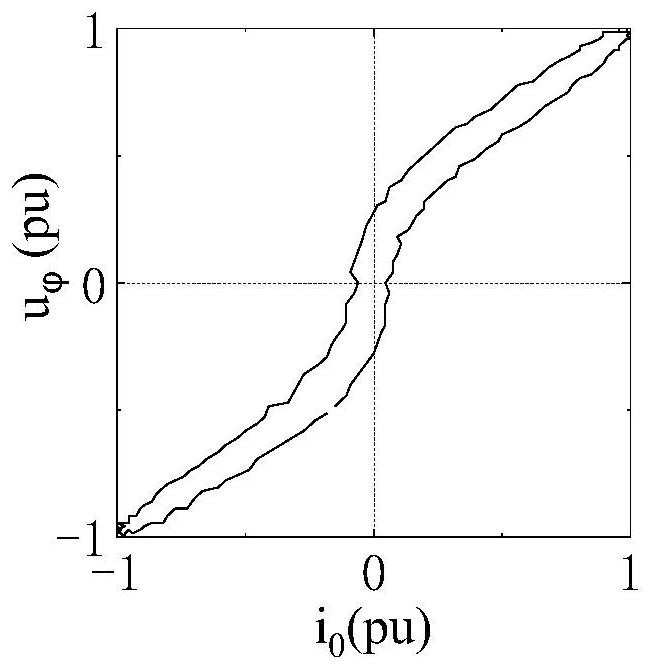
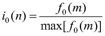
The invention proposes a method and device for judging the direction of a high-resistance fault on a transmission line, collecting a discrete value sequence of a power frequency cycle of the zero-sequence current and three-phase voltage at the protection installation site as an input; Use the full-wave Fourier transform to calculate the phase angle of the power frequency components of each sequence, and use the phase angle difference between the zero-sequence current and phase voltage to select the faulty phase; use the zero-sequence current-phase voltage curve in the first The algebraic sum of the area enclosed by the quadrant and the instantaneous value of the phase voltage within a positive half cycle of the zero-sequence current determines whether the high-resistance fault is in the positive direction or the reverse direction. The invention can be directly applied to the protection device of the transmission line without installing new equipment, and has low cost, small calculation amount and fast response speed.

Description

technical field [0001] The invention belongs to the field of power system fault detection and protection, in particular to a method and device for judging the direction of a high-resistance fault of a power transmission line. Background technique [0002] Affected by factors such as insulator flashover, lightning strikes, and mountain fires, AC transmission lines often cause single-phase high-resistance grounding faults caused by discharges to surrounding tree branches, moso bamboo, and flame discharges through mountains. Traditional AC transmission line protection such as differential protection, zero-sequence current protection, and distance protection are prone to action delays or even refusal to operate in high-impedance ground faults. At present, the high-impedance fault identification methods of AC transmission lines mainly include the impedance principle and the traveling wave principle, but the fault detection method based on the impedance principle has limited resis...

Claims


Application Information

Patent Timeline
Patent Type & Authority Patents(China)
IPC IPC(8): G01R31/08H02H7/26
CPCG01R31/085G01R31/088H02H7/26
Inventor 王宾俞斌任萱谢民董新洲戴长春汪伟邵庆祝于洋张骏王海港王同文丁津津孙辉
Owner TSINGHUA UNIV
Learn More