Transformer internal fault monitoring system and control method thereof

A technology for internal faults and monitoring systems, applied in transformer/inductor components, transformer/inductor cooling, electrical component structure associations, etc., can solve problems such as crowding, transformer oil reduction, transformer failure, etc., and achieve convenient and simple use , good reliability

Inactive Publication Date: 2021-05-28
HANGZHOU KELIN ELECTRIC POWER EQUIP +1
View PDF4 Cites 1 Cited by
  • Summary
  • Abstract
  • Description
  • Claims
  • Application Information

AI Technical Summary

Problems solved by technology

If there is too much gas accumulated on the top of the transformer oil tank, it will inevitably occupy the space occupied by the transformer oil in the transformer, resulting in a decrease in the amount of transformer oil in the transformer oil tank.
The reduction or deterioration of the transformer oil in the transformer oil tank will affect the cooling effect, insulation effect, arc suppression effect and liquid seal effect of the transformer oil on the transformer. not well protected, leading to transformer failure
[0003] At present, the approximate horizontal position of the burnt part of the substation components in the transformer oil tank cannot be determined in the remote monitoring of transformer faults; at present, only when the substation components are taken out of the oil tank for inspection at the scene can the power substation in the transformer tank be known. The approximate horizontal position of the burnt part of the component cannot be determined remotely in the transformer oil tank.
[0004] At present, for the gas generated due to faults in the transformer oil tank, it is generally used to directly discharge the gas in the transformer oil tank by setting an exhaust valve on the top of the transformer oil tank. Remote monitoring and management of internal faults

Method used


Image

  • Transformer internal fault monitoring system and control method thereof
  • Transformer internal fault monitoring system and control method thereof
  • Transformer internal fault monitoring system and control method thereof

Examples


Embodiment Construction

[0104] The present invention will be further described below in conjunction with the accompanying drawings and embodiments.

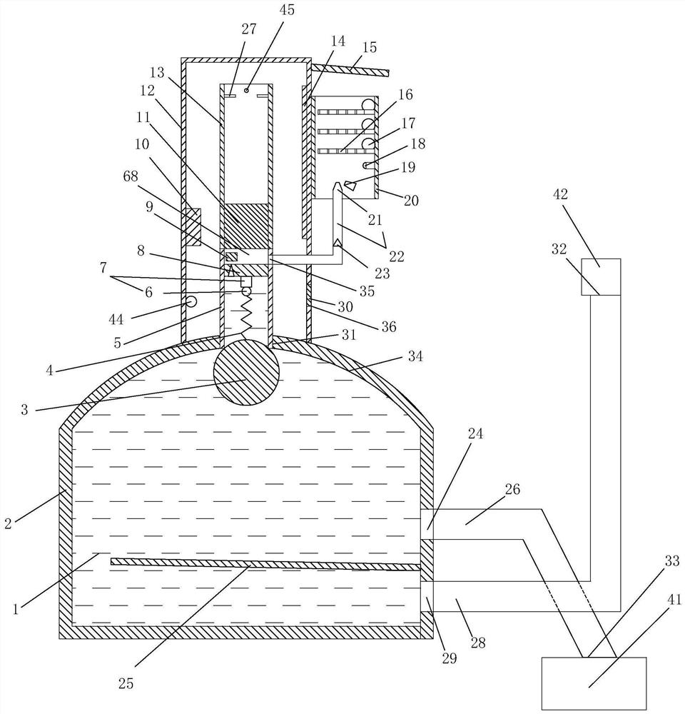
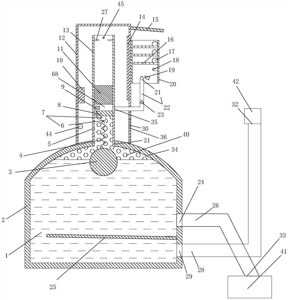
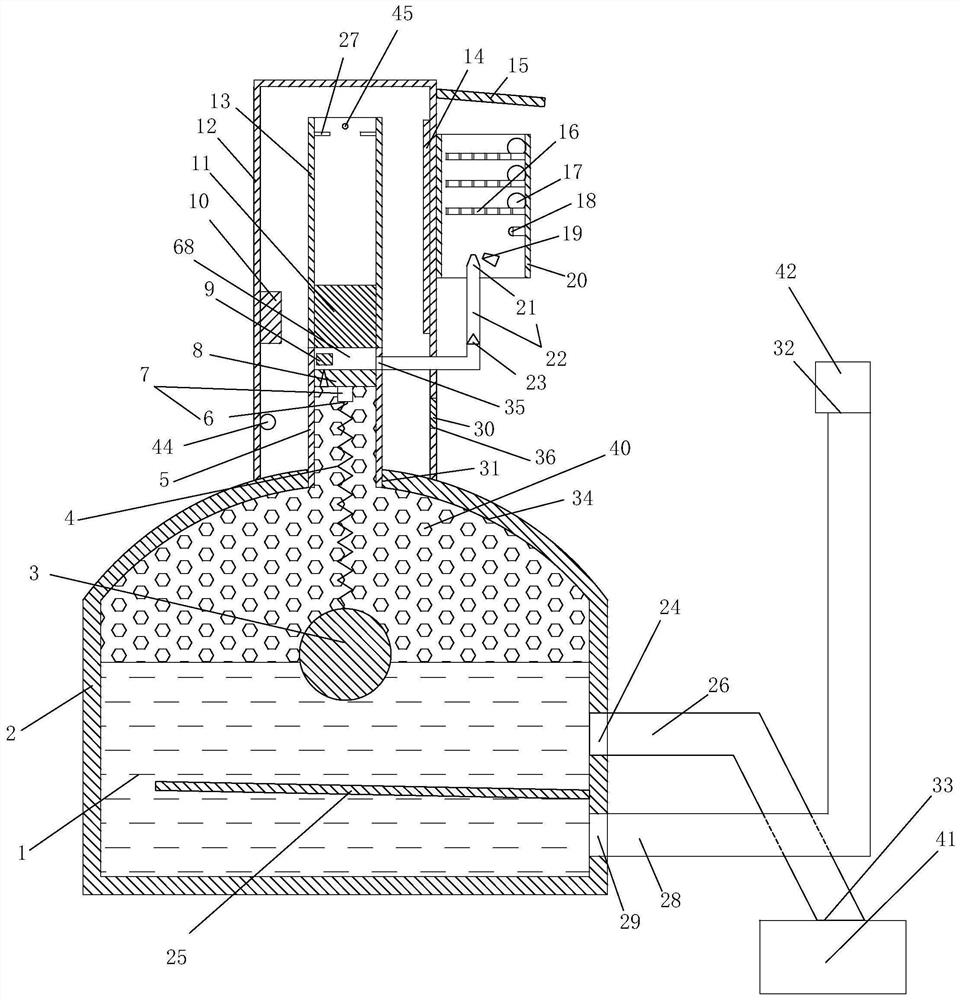
[0105] Embodiment, transformer internal fault monitoring system, see Figure 1-Figure 11 As shown, it includes a transformer oil conservator 42, a transformer oil tank 41, a transformer component 74 sealed in the transformer tank, and a power input column 71 and a power output column 75 arranged opposite to each other at the lower ends of the upper end of the transformer component respectively. The lower end of the power input column and the lower end of the power output column are sealed in the transformer oil tank; it also includes a transformer fault monitoring platform 43, a controller 39, a gas collection fault detection trigger mechanism 79, a gas color observation mechanism 97, a gas odor detection mechanism 98, Gas volume detection mechanism 99, gas flammability detection mechanism 100, bubble horizontal coordinate positioning detection mechanis...


PUM


Abstract

The invention discloses a transformer internal fault monitoring system and a control method thereof, which belong to the technical field of transformer internal fault monitoring equipment, have remote monitoring and management capability, and can perform remote monitoring and management on fault horizontal coordinate positions, fault types and fault severity in a transformer by using gas generated at a burnt-out part of a power transformation part in a transformer oil tank. Asealing box is arranged above thetransformer oil tank, the gas inlet end of a gas color observation mechanism is connected to an upper pipe opening of a first vertical pipe, a gas smell detection mechanism is arranged in the gas color observation mechanism, a gas volume detection mechanism is arranged in the gas color observation mechanism, the gas inlet end of a gas flammability detection mechanism is connected to a side wall exhaust hole of the first vertical pipe, and a bubble horizontal coordinate positioning detection mechanism is arranged in the transformer oil tank.

Description

technical field [0001] The invention relates to the technical field of transformer internal fault monitoring, in particular to a transformer internal fault monitoring system and a control method thereof. Background technique [0002] After the circuit in the transformer oil tank fails, the high-temperature arc generated by the short-circuit current will cause the transformer oil to decompose and generate gas, and will also cause the substation components at the arc to burn out or scorch to generate gas. In addition, the leakage of the transformer oil tank will also allow air to enter the transformer oil tank, and these gases will gather at the top of the transformer oil tank. If there is too much gas accumulated on the top of the transformer oil tank, it will inevitably occupy the space occupied by the transformer oil in the transformer, resulting in a decrease in the amount of transformer oil in the transformer oil tank. The reduction or deterioration of the transformer oi...

Claims


Application Information

Patent Timeline
Patent Type & Authority Applications(China)
IPC IPC(8): H01F27/40H01F27/14H02J13/00
CPCH01F27/14H01F27/402H02J13/00022
Inventor 郑宏聂明军鲍美军李孟赵阿龙卢衍泓詹江扬杨智郑一鸣周建平周国伟
Owner HANGZHOU KELIN ELECTRIC POWER EQUIP
Why Eureka
Try Eureka