
A converter system and its converter cooling water system

A cooling water system and converter technology, applied in the field of converters, can solve problems such as automatic exhaust and inclusions that are not suitable for converter cooling systems

Active Publication Date: 2022-08-02
ZHUZHOU CSR TIMES ELECTRIC CO LTD
View PDF11 Cites 0 Cited by
  • Summary
  • Abstract
  • Description
  • Claims
  • Application Information

AI Technical Summary

Problems solved by technology

[0004] However, for the converter water cooling circulation system with a high flow rate, the air is trapped in the cooling water, making it difficult for the existing automatic exhaust device to gather air from the converter cooling water system into the exhaust device
Therefore, the existing automatic exhaust device is not suitable for the automatic exhaust of the converter cooling system

Method used


Image

  • A converter system and its converter cooling water system
  • A converter system and its converter cooling water system
  • A converter system and its converter cooling water system

Examples


Embodiment Construction

[0039] The technical solutions in the embodiments of the present invention will be clearly and completely described below with reference to the accompanying drawings in the embodiments of the present invention. Obviously, the described embodiments are only a part of the embodiments of the present invention, but not all of the embodiments. Based on the embodiments of the present invention, all other embodiments obtained by those of ordinary skill in the art without creative efforts shall fall within the protection scope of the present invention.

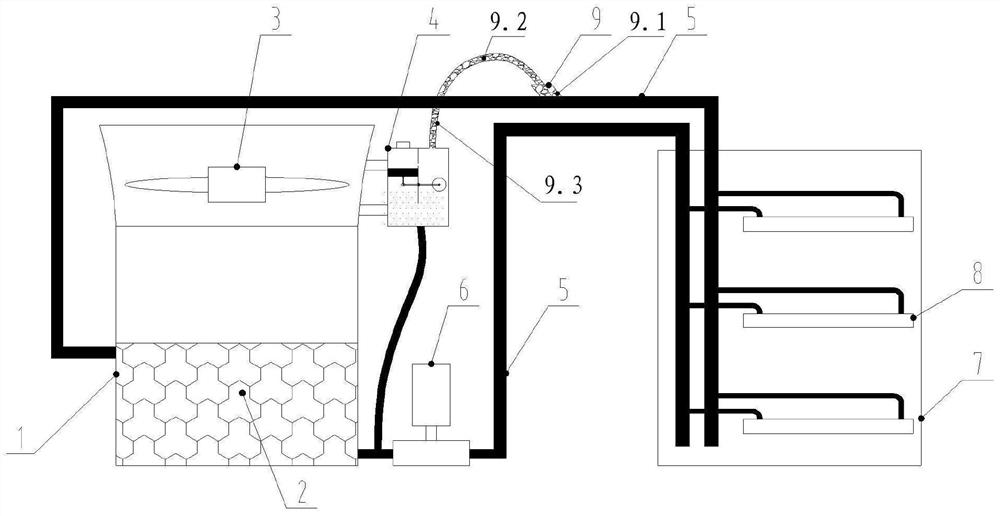
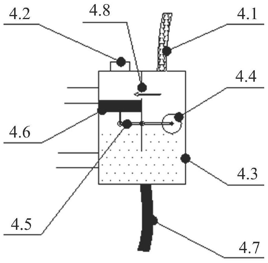
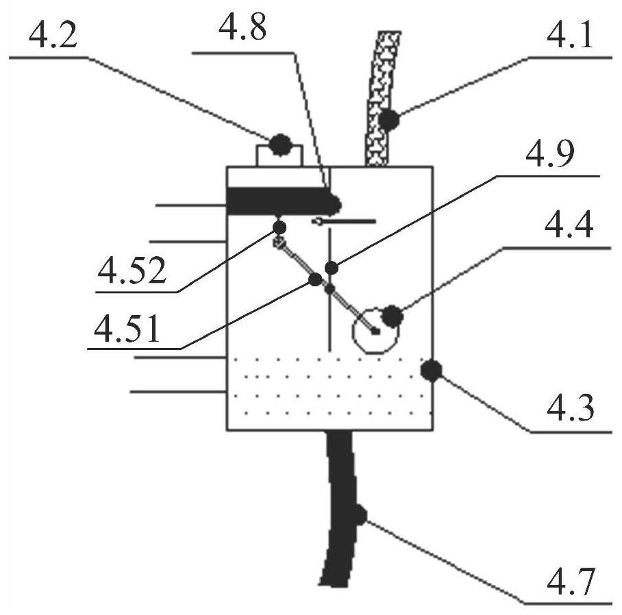
[0040] The converter cooling water system provided by the embodiment of the present invention, such as figure 1 As shown, including: cooling water pipeline 5, automatic exhaust box 4 and gas collecting pipe 9;

[0041] The cooling water pipeline 5 is located at the highest position on the top of the cooling water system of the converter; the gas collector inlet of the gas collector 9 is connected to the cooling water pipeline 5, and a...


PUM


Abstract

The invention discloses a converter system and a converter cooling water system, wherein the converter cooling water system comprises: a cooling water pipeline, an automatic exhaust box and a gas collecting pipe; the cooling water pipeline is located in the converter cooling water The highest position at the top of the system; the inlet of the gas header is connected to the cooling water pipeline, and at least the inlet part of the gas header is located above the cooling water pipeline, and the outlet of the gas header is connected to the exhaust box inlet of the automatic exhaust box; when When the gas pressure value in the automatic exhaust box is greater than the preset critical pressure value of the automatic exhaust box, the automatic exhaust box can automatically discharge the gas. In this solution, the gas collecting pipe is connected above the highest pipeline at the top of the cooling water system of the converter, so that the entrained air with high flow velocity can float into the gas collecting pipe through the buoyancy effect of the gas, so as to realize the control of the entrained air. collected, and then flowed into the automatic exhaust box, thereby realizing automatic exhaust of the cooling water system of the converter.

Description

technical field [0001] The invention relates to the technical field of converters, in particular to a converter system and a converter cooling water system. Background technique [0002] The exhaust of the cooling water system of the converter is a necessary requirement for the maintenance of the cooling water system of the converter. If there is a lot of air in the system, it will cause cavitation of the circulating water pump of the cooling water system, reducing the flow rate, and the inclusion of air bubbles in the water flow will lead to heat transfer. The effect is reduced, which seriously affects the reliable operation of the converter. [0003] In the existing automatic exhaust device, it is suitable for the cavity structure with large internal space, simple structure and easy accumulation of air. [0004] However, for the converter water cooling circulation system with a high flow rate, air is entrained in the cooling water, making it difficult for the existing aut...

Claims


Application Information

Patent Timeline
Patent Type & Authority Patents(China)
IPC IPC(8): H05K7/20H02M1/00
CPCH05K7/20927H02M1/00
Inventor 朱宇龙张宾毛康鑫刘清蒋奉兵何维李昆徐江辉李敏
Owner ZHUZHOU CSR TIMES ELECTRIC CO LTD
Learn More